Discontinued
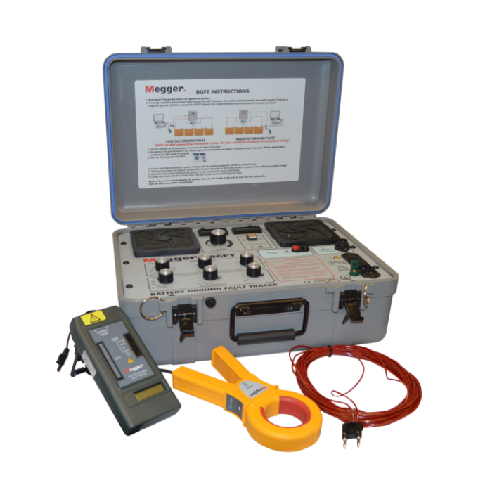
BGFT battery ground fault tracer
About the product
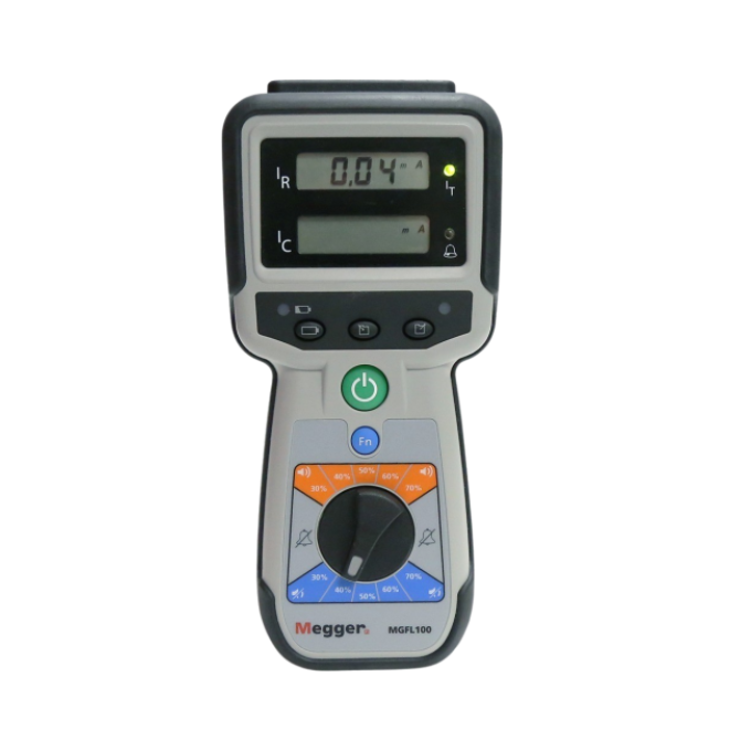
Suggested replacement for this discontinued product is the MGFL100
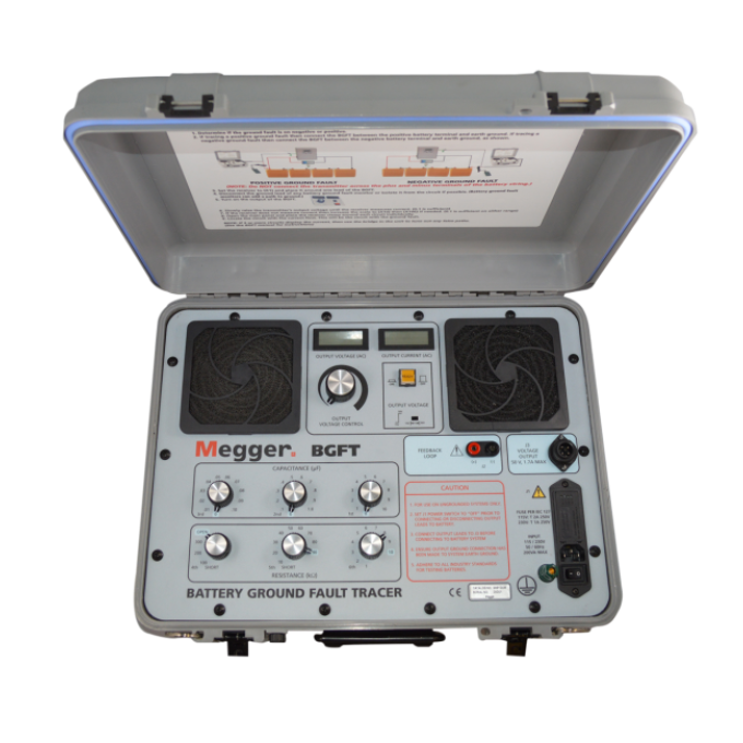
The BGFT battery ground fault tracer is a dual range, economical, easy-to-use instrument that identifies, traces and locates ground faults in ungrounded DC systems. It’s particularly effective in environments with high electrical noise as the strength of the test signal can be adjusted.
The BGFT comes with a dual range (high/low power switch), providing you with the ability to locate high impedance faults with the switch in the 50 V range, and providing added safety in the 15 V range.
The instrument also makes fault location quick as it eliminates trial-and-error procedures and can locate faults while the system is still energised. As such, it is particularly useful in any industry where the supply of power for operating measurement, communication and control equipment is critical.
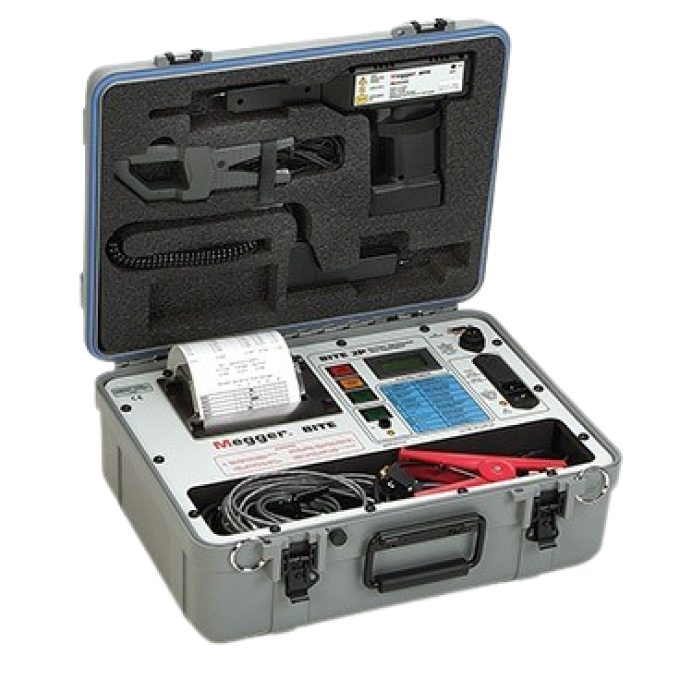
Related products
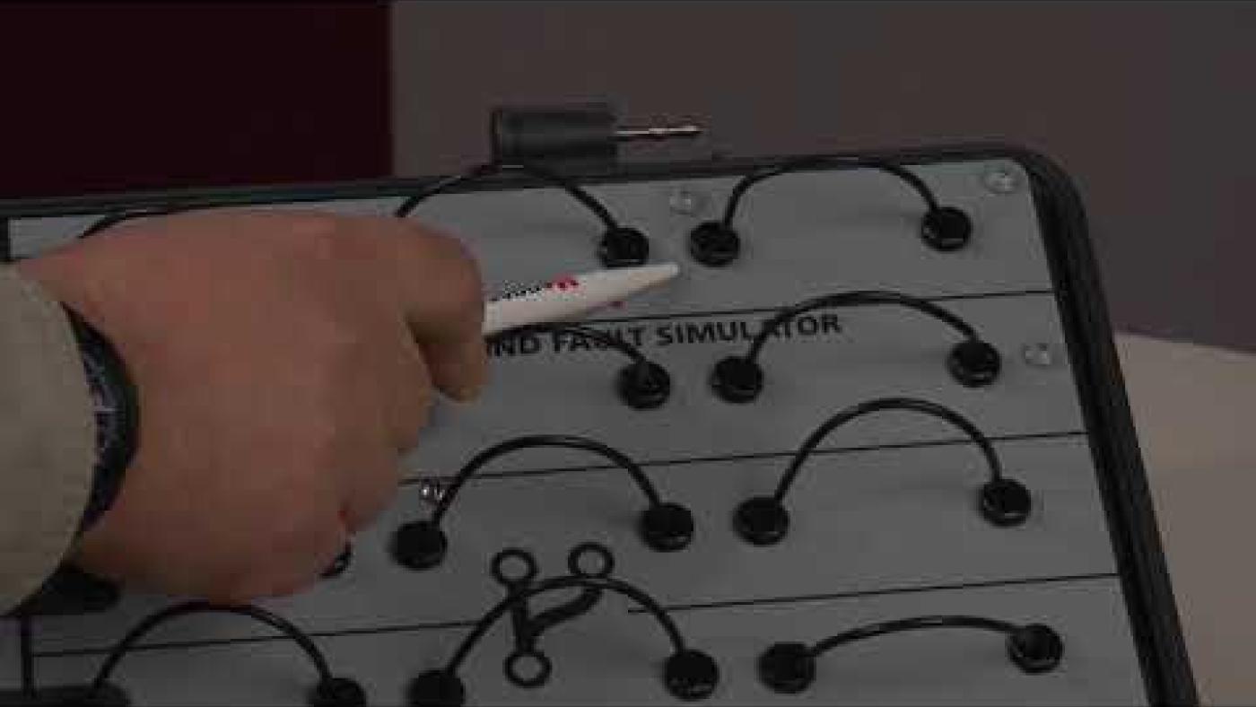
Using your product


