ICMmonitor on-line partial discharge monitor


About the product
The ICMmonitor on-line partial discharge monitor continuously monitors the condition of the insulation system of your medium and high voltage (MV and HV) assets and gives you the ability to analyse the acquired data. The in-depth analysis of the trending information delivered by the ICMmonitor enables you to detect defects in an early state and prevent costly failures.
The ICMmonitor combines three devices into one instrument: A spectrum analyser, an acoustic detector, and a partial discharge (PD) monitor. The combination of spectrum analyser and PD detector greatly expands the measurement possibilities when analysing the insulation systems in a noisy environment. Thus, the ICMmonitor offers continuous PD on-line monitoring and excellent measurement results, even with a large amount of electrical noise.
With the monitoring web server function (MWS) you can remotely access the ICMmonitor instrument and see topical information on your asset’s condition. Additionally, you can receive an email notification in the case of system errors.
The ICMmonitor can be used for monitoring the following assets:
- Power transformers
- Motors
- Generators
- Cable systems
Standard features of the ICMmonitor are:
- PD spectrum analysis for the selection of frequency bands with less disturbances, resulting in an improved signal-to-noise ratio.
- A built-in four-channel multiplexer offers scanning of three-phase systems or multiple sensors, with each measurement channel separately configurable.
- Effective noise gating for blocking phase-stable or phase-independent noises
- Automatic data acquisition and storing for trend analysis, alarming, and reporting
- UHF measurements
The instrument is available with a wide range of optional features, giving it flexible installation and a range of configuration options that can meet your specific need.
Available features are:
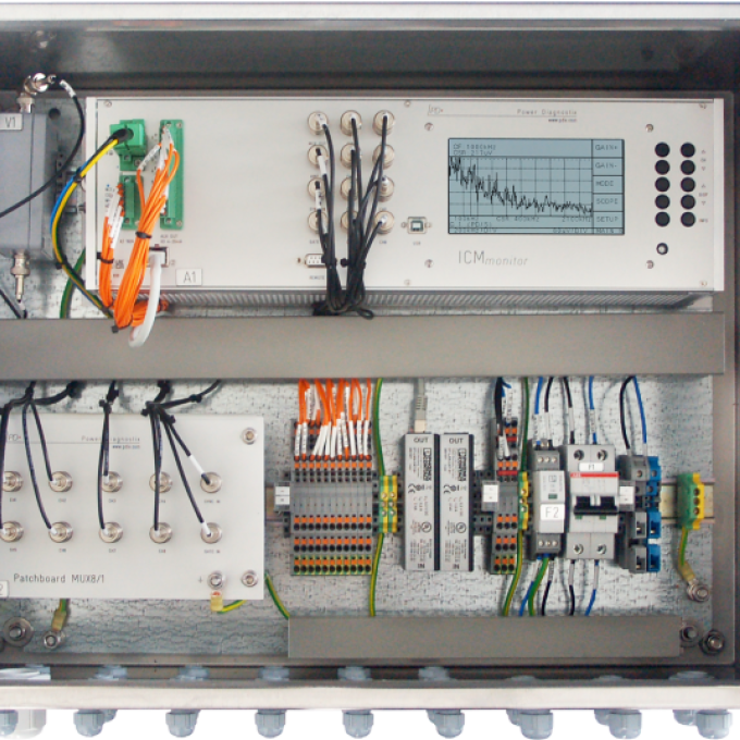
- Industrial monitoring cabinet with necessary supply and safety components pre-installed, suitable for outdoor installation
- Specialised control software for remote access and download of stored trending data.
- Eight-channel multiplexer.
- Monitoring web server for web browser based remote access and control from everywhere in your network.
- Mobile communication interface for remote access via UMTS
- Up to four additional output signals for external monitoring purposes.
- Up to six additional inputs for sensor signals.
- IEC 61850 interface.
- Built-in preamplifier.
- Pre-installed control PCs or notebooks.
- Expert software for PD pattern classification according to their PD faults.
Power Diagnostix’s ICMmonitor is equipped with a serial computer interface for the download of trending data and remote access, e.g., by LAN network (TCP/IP) or USB. Special software allows the remote control of the instrument, data evaluation, and in-depth diagnosis of the acquired data. This service software provides easy access to view, compare, and analyse the stored data.
Additionally, the optional monitoring web server (MWS) provides an Ethernet gateway for a platform-independent remote access to monitoring data recorded with the ICMmonitor. Alarms triggered by the instrument can be reported by automated email to the responsible person.
Combined with an LTE mobile router, a secure remote access via the Internet can be provided.

Additional videos

Troubleshooting
In the Windows Device Manager if the USB driver is properly installed.
If the automatic installation of the USB driver fails, it's possible to install the driver manually. Manual installation is divided into two steps due to the driver properties:
Step 1: Open the Windows Device Manager. Select “Silicon Labs CP210X USB to UART Bridge”, which is listed as an item of “Other devices”. Right-click on it and select “Update Driver” from the context menu.


The “Hardware Update Wizard” will open. Select “Search for the best driver in these locations” and specify the directory, where the ICMmonitor software has been installed, as shown in the figure above. Click “Next” to proceed. Windows will now install the first part of the driver software, the USB controller driver:
Usually, the installation will end with an error message, since the second part of the driver – the USB bridge driver – is still missing. Repeat the steps above to install the second part of the CP210X bridge driver. If the installation is completed successfully, the CP210X device should appear in the “Device Manager”.

On PCs running Windows 10 with the Creator’s Update (2017) the ICMmonitor application window may appear very small on high resolution monitors. To enlarge the display size of the software, please take the following steps:
- Right-click on the application short cut on the desktop.
- Choose "Properties" from the context menu. This will open the “Properties” window.
- On the “Compatibility” tab, enable “Override high DPI scaling behaviour” and set “Scaling performed by” to “System”.
- If you have administrator rights, you can change the settings for all users by clicking the corresponding button.
- Approve the change by clicking “OK”.
The preamplifier must be enabled if an RPA is connected. Ensure that “>RPA ON” is marked in the instrument menu.
If this fails to resolve the issue, try substituting the BNC cables to be sure that the problem is not in the cables themselves. Replace the cables if they are faulty.
If the cables are not the issue, please contact our technical support team to discuss the next troubleshooting steps.
- First check that the calibrator is still on. The calibrator will shut off automatically after about 15 minutes without having one of its buttons pushed. Check that the low battery indicator is not visible on the LCD of the calibrator.
- The calibration pulse setting might be too weak for the test setup. Try increasing the magnitude of the calibration impulse applied to the test setup.
- The calibration pulse on-screen might be present but too small to be easily visible. Try putting the ICMmonitor into “NORM” mode Menu: SCOPE ► MODE ► NORM). This will make the calibration pulse appear as a vertical bar, which makes it easier to see on-screen that it appears in the “HOLD” mode.
- Sometimes the calibration pulse is lost if the high voltage power supply is connected to the test setup when the calibration is performed, even if the high voltage supply is completely powered off. Ensure that the power supply is not earthed during calibration. Try physically disconnecting the high voltage supply from the test object during the calibration process. The calibrator is then only connected via the quadrupole of the test object and the coupling capacitor (if present).


