ICMmonitor Portable portable partial discharge monitoring system

About the product
The ICMmonitor Portable partial discharge (PD) monitoring system from Power Diagnostix ’s ICMmonitor Portable is a compact non-invasive PD monitor for continuous on-line evaluation of the insulation condition of medium and high voltage (MV and HV) assets. The instrument is used principally for temporary on-line monitoring and spot testing of:
- Power transformers
- Motors
- Generators
- Cable systems
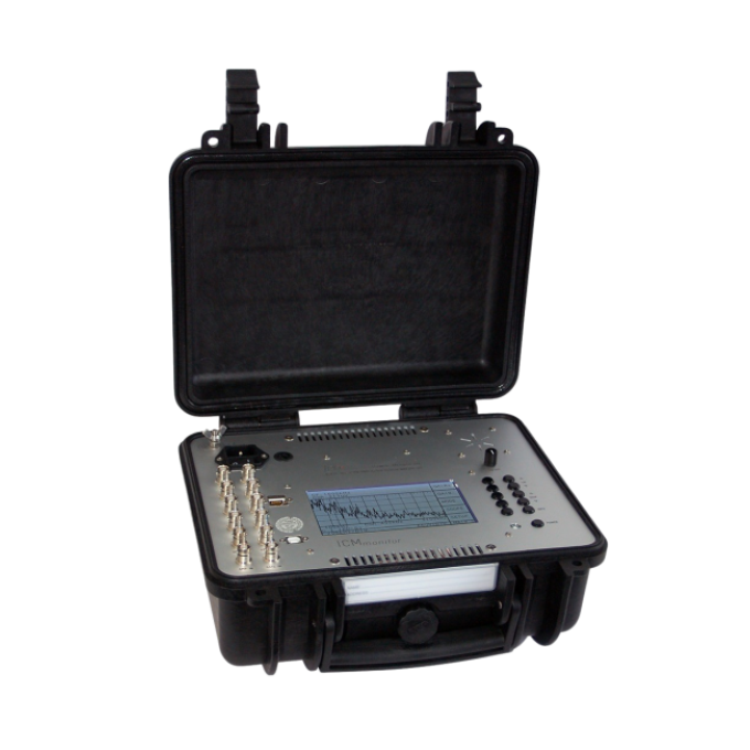
The ICMmonitor Portable comprises a spectrum analyser, an acoustic detector, and a conventional PD monitor in one instrument. This combination enables PD measurements, even with high levels of background noise, on assets such as power transformers within substations or power plants.
Its built-in multiplexer allows you to scan three-phase systems or multiple sensors, and its simple push-button interface and on-screen menus, located in an embedded LCD panel, make it incredibly easy to use.
The display modes include, a horizontal bar graph display, monochrome phase-resolved PD patterns for classification of defects, a scope-like display showing phase-summed charge pulses superimposed with the applied voltage wave, and a spectrum display showing the frequency spectrum of the acquired signals.
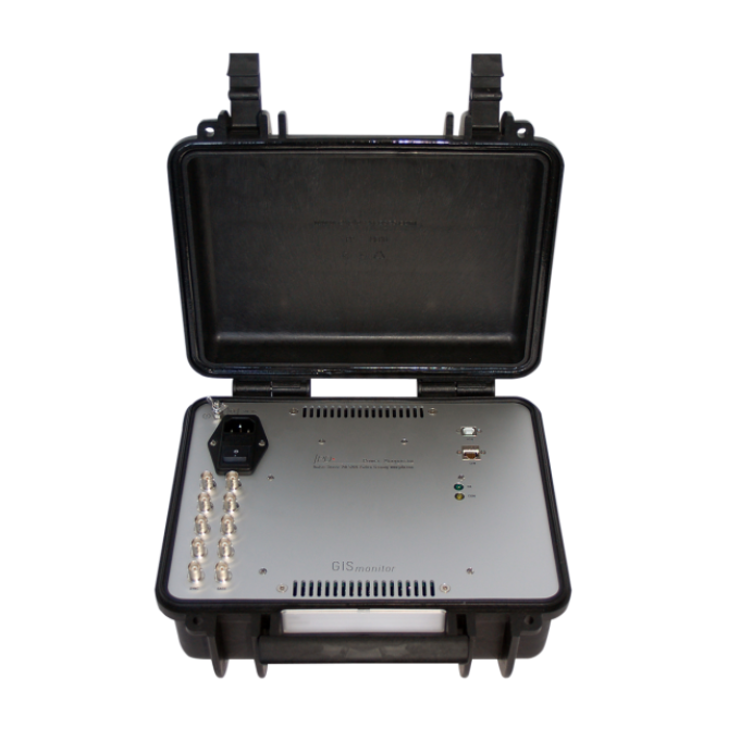
Power Diagnostix’s ICMmonitor Portable is an autonomous instrument that, can be used as stand-alone monitoring device. It is equipped with a serial computer interface for the download of trending data and remote access, e.g., by LAN network (TCP/IP) or USB. Special software allows the remote control of the instrument, data evaluation, and in-depth diagnosis of the acquired data. This service software also provides easy access to view, compare, and analyse the stored data.

Additional videos

Troubleshooting
The power fuse might be blown. Unplug the unit and check the power supply fuse. This fuse is located in the upper left corner above the on/off switch.
A communications error with the serial connection to the ICMmonitor might have occurred. Within the ICMmonitor software, check that the serial COM port selected in the menu “Connect” is the COM port to which the ICMmonitor is connected. Then try rebooting both the ICMmonitor and the PC.
Within the “Windows Device Manager”, check if the USB driver is properly installed. Then try rebooting the ICMmonitor Portable and the PC.
If the automatic installation of the USB driver fails, it's possible to install the driver manually. Manual installation is divided into two steps due to the driver properties:

Step 1: Open the “Windows Device Manager”. Select “Silicon Labs CP210X USB to UART Bridge”, which is listed as an item of “Other devices”. Right-click on it and select “Update Driver” from the context menu.
The “Hardware Update Wizard” will open. Select “Search for the best driver in these locations” and specify the directory, where the ICMmonitor software has been installed, as shown in the figure above.

Click “Next” to proceed. Windows will now install the first part of the driver software, the USB controller driver.
Usually, the installation will end with an error message, since the second part of the driver – the USB bridge driver – is still missing.
Repeat the steps above to install the second part of the CP210X bridge driver. If the installation is completed successfully, the CP210X device should appear in the “Device Manager”.

The ICMmonitor application widow appears very small on high resolution monitors on Windows 10
On PCs running Windows 10 with the Creator’s Update (2017) the ICMmonitor application window may appear very small on high resolution monitors. To enlarge the display size of the software, please take the following steps:
- Right-click on the application short cut on the desktop.
- Choose "Properties" from the context menu. This will open the “Properties” window.
- On the “Compatibility” tab, enable “Override high DPI scaling behaviour” and set “Scaling performed by” to “System”.
- If you have administrator rights, you can change the settings for all users by clicking the corresponding button.
- Approve the change by clicking “OK”.
The preamplifier must be enabled if an RPA is connected. Ensure that “>RPA ON” is marked in the instrument menu.
If this fails to resolve the issue, try substituting the BNC cables to be sure that the problem is not in the cables themselves. Replace the cables if they are faulty.
If the cables are not the issue, please contact us at [email protected] to discuss the next troubleshooting steps.
- First check that the calibrator is still on. The calibrator will shut off automatically after about 15 minutes without having one of its buttons pushed. Check that the low battery indicator is not visible on the LCD of the calibrator.
- The calibration pulse setting might be too weak for the test setup. Try increasing the magnitude of the calibration impulse applied to the test setup.
- The calibration pulse on-screen might be present but too small to be easily visible. Try putting the ICMmonitor into “NORM” mode by going to “Menu” > “: SCOPE” > “MODE” > “NORM”). This will make the calibration pulse appear as a vertical bar, which makes it easier to see on-screen as it appears in the “HOLD” mode.
- Sometimes the calibration pulse is lost if the high voltage power supply is connected to the test setup when the calibration is performed, even if the high voltage supply is completely powered off. Ensure that the power supply is not earthed during calibration. Try physically disconnecting the high voltage supply from the test object during the calibration process. The calibrator is then only connected via the quadrupole of the test object and the coupling capacitor (if present).


