ODEN AT primary current injection test system
About the product
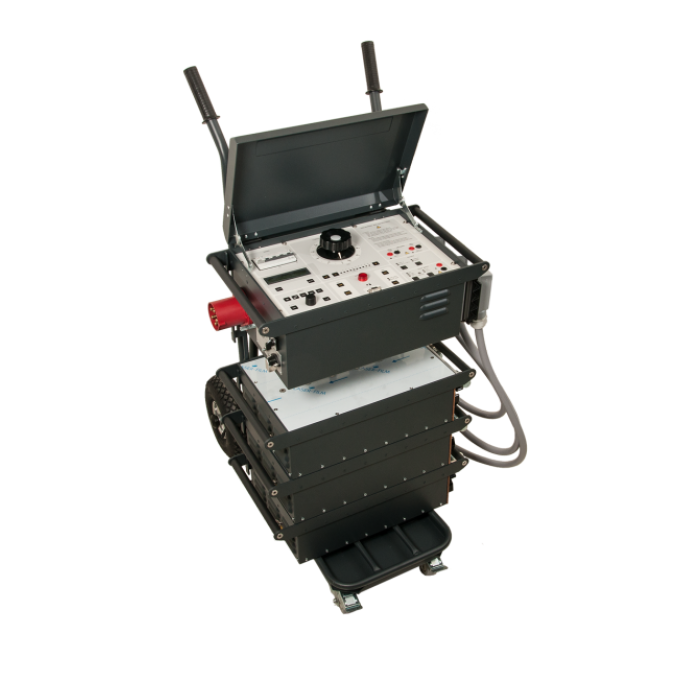
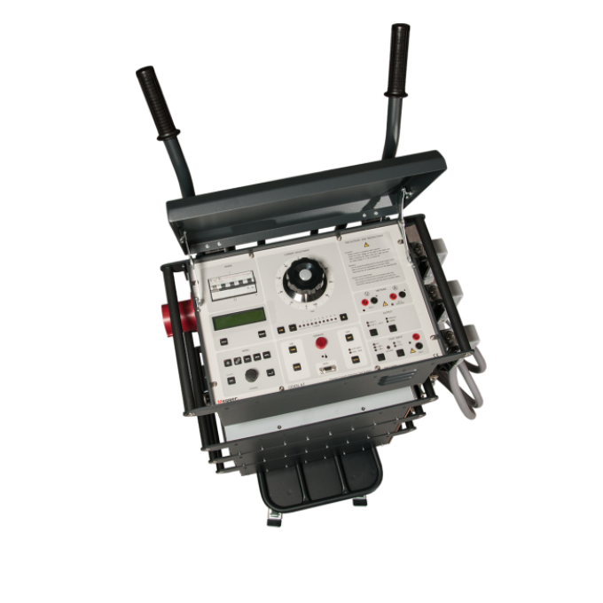
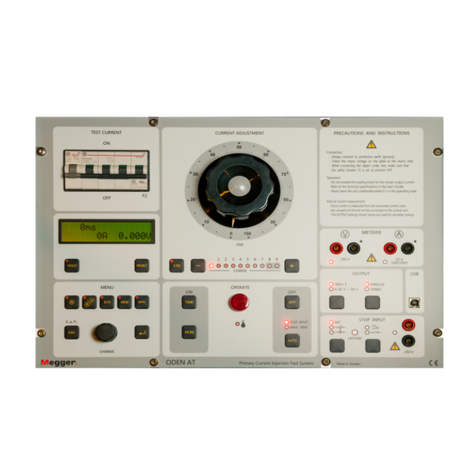
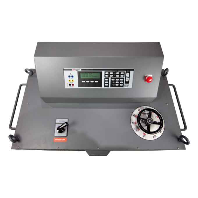
Megger has specially designed the ODEN AT primary current injection test system for testing circuit breakers (CBs) and protective relay equipment. You can also use it to test the turns ratio of current transformers and for other applications that require high variable currents. Additionally, you can set the ODEN AT to test circuit breakers with reclosing relays and sectionalisers, and it is ideal for performing heat runs as the current can be applied continuously or through programmable intervals. The ODEN AT can also test the integrity of earth/ground grids and safety-ground devices.
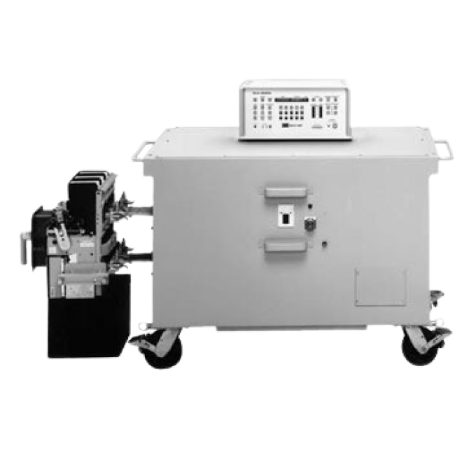
The system consists of a control unit with one, two, or three current units. The current unit has three versions: S, X, and H. The S and X current units are identical, except the X unit has an additional 30/60 V output. The H unit is rated for an even higher current. These current units make it possible to configure the ODEN AT system for various tests.
The control unit has many advanced features, such as a powerful measurement section that can display turns ratio and time, voltage, and current. You can also make use of a second measurement channel to test an additional current or voltage. The ODEN AT can calculate the current transformer turns ratio, impedance, resistance, power, power factor, and phase angle.
The current and voltage can be presented as percentages of nominal value. It also has a fast-acting hold function that freezes short-duration readings on the digital display, so when the voltage or contact signal arrives at the 'stop' input, the object under test interrupts the current, or the injection is stopped.
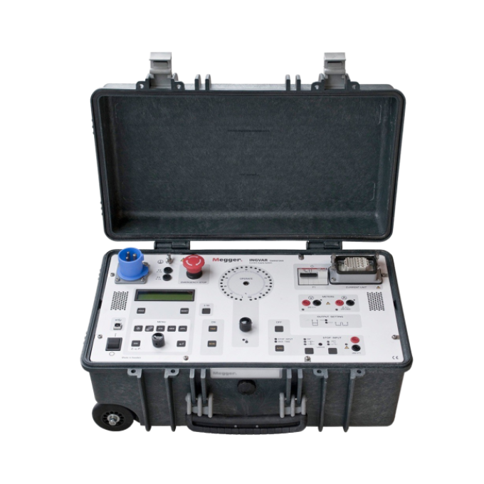
All parts are portable, and the ODEN AT can be quickly disassembled, assembled, and connected.
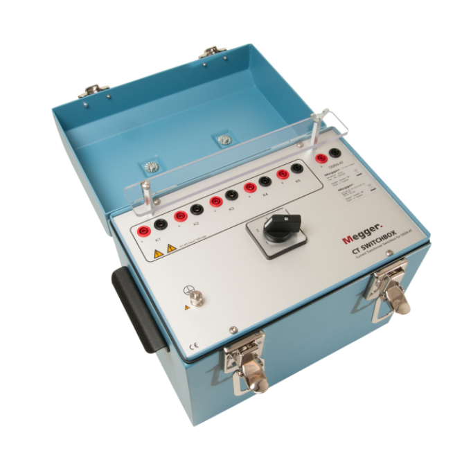
Related products
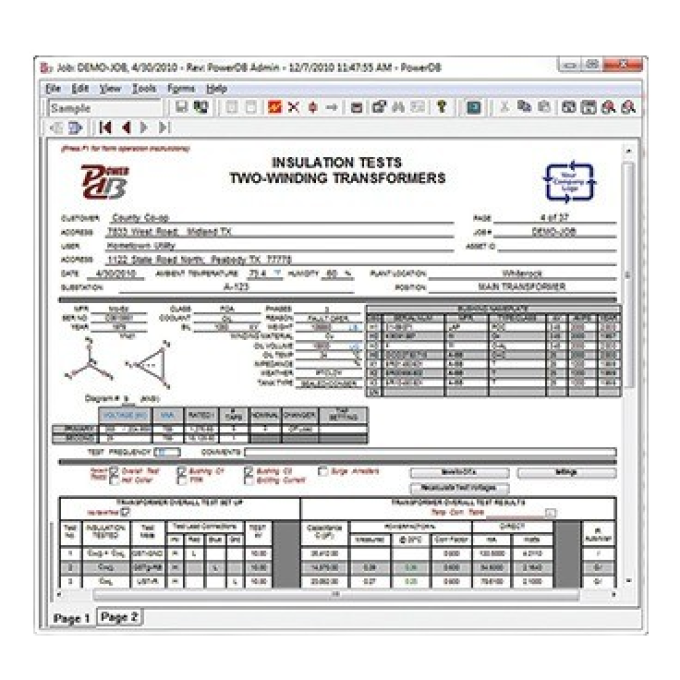
Interpreting test results
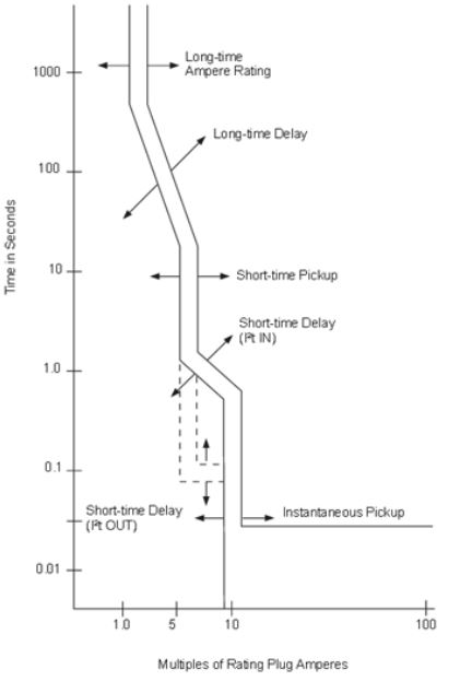
Proper primary injection testing of low voltage circuit breakers (LVCB) will confirm that they trip at the correct times and can properly isolate a fault. A coordination study is performed, and parameters are set to minimise the amount of interruption to other equipment. The characteristics of the circuit breakers are presented in the form of trip curves, and each circuit breaker will have a unique trip curve published by the manufacturer. The trip curves will have bands, or limits, that show how long it takes for the circuit breaker to trip when a certain amount of current is applied; the current is typically presented in multiples of the rated current. As long as the circuit breaker trips within the specified band, it operates correctly. You may perform up to four primary injection test types to verify that the LVCB is working correctly: a long time test, short time test, instantaneous test, and earth/ground fault test. The long, short, and ground fault tests all have a delay component. In contrast, the instantaneous test trips the circuit breaker immediately.
The long time test is a test of the overload function and requires two settings. The first setting is the pickup, which determines the load current level that is tolerable before an overload condition occurs. The second setting is the time delay that determines how long the overload condition is acceptable. Systems are generally designed to handle overload conditions for a short time. Still, damage will occur if the overload persists for too long. You typically perform a long time test at 3 times the rated current.
The short time test is also an overload test with a pickup time like the long time test but has a shorter duration with a higher current. Typical currents are at 6 times the rated current. A short time setting on the breaker is used to allow high current loads for a short duration, for example, a motor starting.
The instantaneous trip conditions test the breaker under fault conditions. Therefore, there is no intentional time delay built in, and the breaker should trip within milliseconds. If the circuit breaker fails to trip and clear the fault, this may result in damage to equipment or personnel. Additionally, an upstream breaker may need to clear the fault, resulting in other electrical system components unrelated to the fault being shut down. An instantaneous trip is typically tested using 8 to 12 times the rated current.
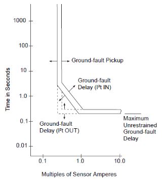
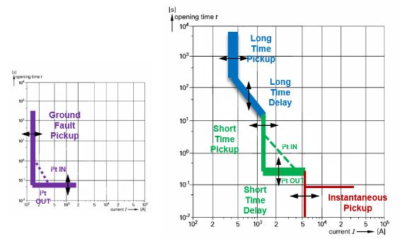
An earth/ground fault trip in the circuit breaker occurs when higher-than-normal currents flow through the ground path. Like the long time and short time functions, the ground fault has both a pickup current and a delay time. Both can be adjusted to fit the coordination study. There is typically a maximum delay that is permitted from ground fault conditions.
Each test is performed separately for each phase. As long as the trip time falls between bands on the time-current curves, the circuit breaker is considered to be in working condition.
Note: the ground fault sensor must be disabled to test long, short, and instantaneous trips.


