GISmonitor partial discharge monitoring system
Parallel UHF PD measurement on all channels
Parallel monitoring of all PD sensors in one or even multiple GIS
Compatible with all UHF sensors for GIS systems
Suits all currently known ultra high frequency (UHF) sensors available on the market for GIS systems
Real-time PD acquisition and analysis
Detects any UHF signal and digitises within microseconds
Parallel readings
Measures PD peak values, PD scope amplitudes, and PD patterns
Automatic noise separation techniques via intelligent software analysis
A separation of PD events from external disturbances or internal switching pulses is provided by the advanced GISmonitor software
About the product
When it comes to Partial Discharge (PD) monitoring, Power Diagnostix’s GISmonitor is the perfect choice for the job. The main task of the GISmonitor is to provide the user with a reliable Partial Discharge Monitoring System (PDMS) capable of detecting defects hidden inside the Gas Insulated Switchgear (GIS) such as hopping particles, floating potential, cracks in insulators, protrusion or other degradation in the insulation system.
The system’s hardware has been optimised for continuous, parallel and real-time PD acquisition in order to record each signal coming from the pre-installed UHF sensors inside the GIS enclosure, no PD activity is left undetected.
The Frequency Converter Units (FCU2) pick up the UHF signal from the embedded UHF sensor and demodulates it into a lower frequency band for easy transmission over longer distances. Special Input Protection Units (IPU2B) placed at the output of the UHF sensors block strong signals, such as very fast transients (VFT), and protect the PDMS.
Each UHF sensor is connected to an acquisition cabinet (PDMAR) that process the data before sending it to the control cabinet (PDMCR): each of these acquisition units can be connected up to 120 UHF sensors. With very few acquisition cabinets, Power Diagnostix’s GISmonitor can therefore cover even the largest GIS and thanks to its modular approach it is highly extendable in case of future extension of the switchgear.
The acquired and processed data is sent through fiber optic ring network to the control unit (PDMCR) where the user can directly operate and have a complete overview of the status of the GIS. In order to ensure that a proper analysis of the measured PDs can be conducted, the GISmonitor software provides the user with a various set of features and options. Through a monitoring mode the operator can access to the historical and live analysis of years of measured data in just a click while also checking the PD event list that summarizes the most critical acquired signals. All the data is collected, stored and automatically analysed in one central server and a database for automatic recognition of particular defects is provided (ICMexpert).
Dedicated features for pre-energization activities are part of the GISmonitor software. A Sensitivity Verification mode, with CIGRE TBA 654 compliancy, reduces to a minimum the requested time for the commissioning of the PDMS and automatically generate a report for the customer. The sensible HV Test that is performed before the energization of a GIS is supported by a dedicated HV Test mode that allows the user to record PD levels and applied voltage simultaneously creating therefore a replay that can be viewed anytime: this constitutes a fingerprint of the substation at the moment of the test.
The PDMS generates and forwards alarms to the subordinated system, such as SCADA, in the exact moment as they are raised, through different interfaces such as potential-free relays or IEC61850 communication protocol.
In case the GIS to monitor is not provided with embedded UHF PD sensors, Power Diagnostix can offer also a series of accessories and external sensors optimized for retrofitting.
buffer text
Further reading and webinars
Related products
Troubleshooting
Check that the power is on for the cabinet and make sure there is power to the plug-in board.
- Make sure the cabling is properly connected.
- Check that the plug-in board is indicating that the initialisation is correct - green LED will be lit up if so
- Reset the alarm in the GISmonitor control software
Check the cabinet for damage or visual signs of any problems. Reactivate the MCB and reset the alarm in the GISmonitor control software.
You should:
- Bridge out the uninterrupted power supply (UPS) on the back of the cabinet.
- Measure the insulation resistance of the cabinet power supply.
- Disconnect all components from their terminals until the insulation resistance is acceptable. The criterion is R > 0.2 MΩ.
- If possible, reset the alarm in the GISmonitor control software (this depends on the component).
- Report the affected component to Power Diagnostix.
You should:
- Check that the power is on for all cabinets
- Check the switches on the hat rail of the cabinets to identify the open connection
- Ports 7 and 8 must show a green LED
- Check the FO cabling between the affected switches
- Repair the FO cable
- Check the system for normal operation
- Reset the alarm in the GISmonitor control software
The cabinet’s overvoltage (OV) protection module has activated, and it needs replacing.
You should:
- Check the cabinet for damage and adequate function
- Unplug the OV protection module
- Plug in a new module
- Reset the alarm in the GISmonitor control software
This means the uninterrupted power supply (UPS) is using the battery, due to a missing power supply.
You should:
- Check if the MCB has tripped
- Measure the power supply
- Check all cables to ensure the connections secure
- Reset the alarm in the GISmonitor control software
You should:
- Check the back of the UPS and find the thermal fuse
- Reset the thermal fuse by pressing the red button
- Test if the system has returned to normal functionality
- Reset the alarm in the GISmonitor control software
This message indicates that you must replace the UPS battery.
You should:
Contact the UPS manufacturer or Power Diagnostix for a new battery and follow the manufacturer’s battery replacement instructions.
Interpreting test results
The evaluation of a PRPD pattern, enables you to determine the kind of fault within the test object. Most partial discharge (PD) faults, such as insulation damages, voids, surface discharges, or floating points, will have completely different PD patterns. The typical criteria for classifying these patterns are:
- Phase position of the maximum partial discharge
- Phase position of the starting electron
- The gradient of discharges
- The shape of discharges in the positive and negative half-cycle
- The absolute value of discharge in pC or nC
- Short-time or continuous discharges
For successful interpretation, it is also necessary to get as much information as possible about the test object and its environment. Such information could include temperature, installation condition, age of the test object, previous faults, or weather conditions.
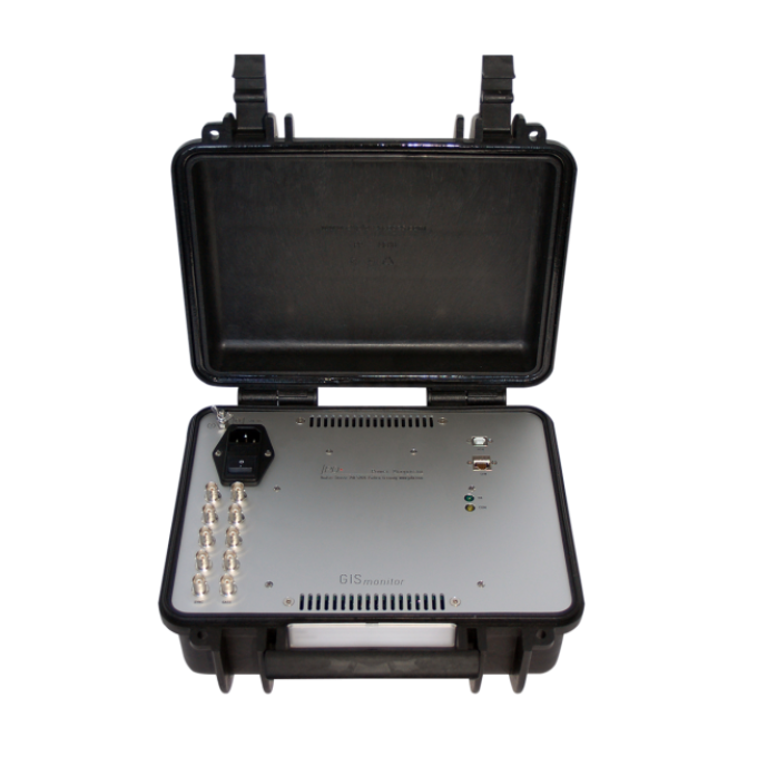
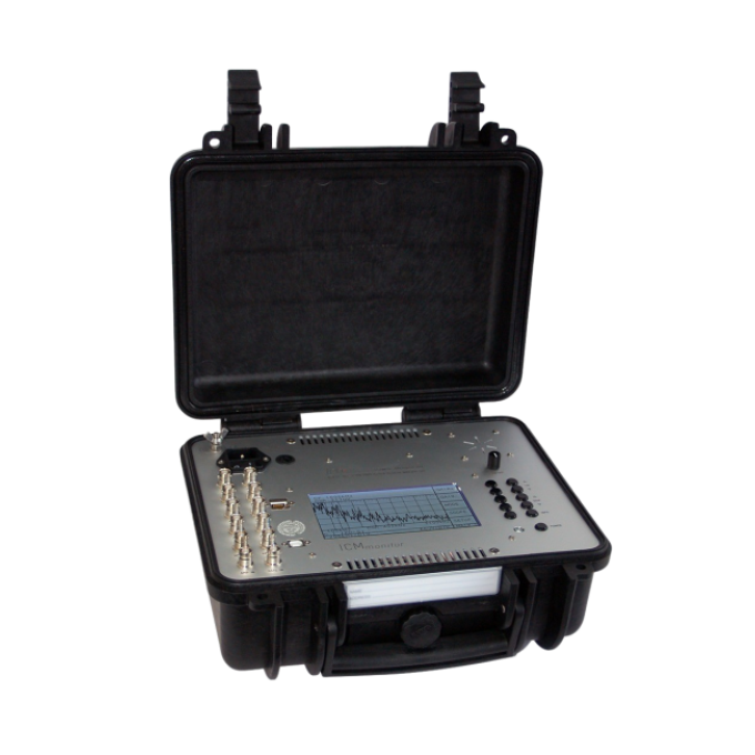
It is useful to store typical PD patterns of known faults in an archive. This, can be done by using the GISmonitor software in combination with Power Diagnostix’s ICMexpert software. This customer-specific database will be helpful for later evaluation on other test objects.