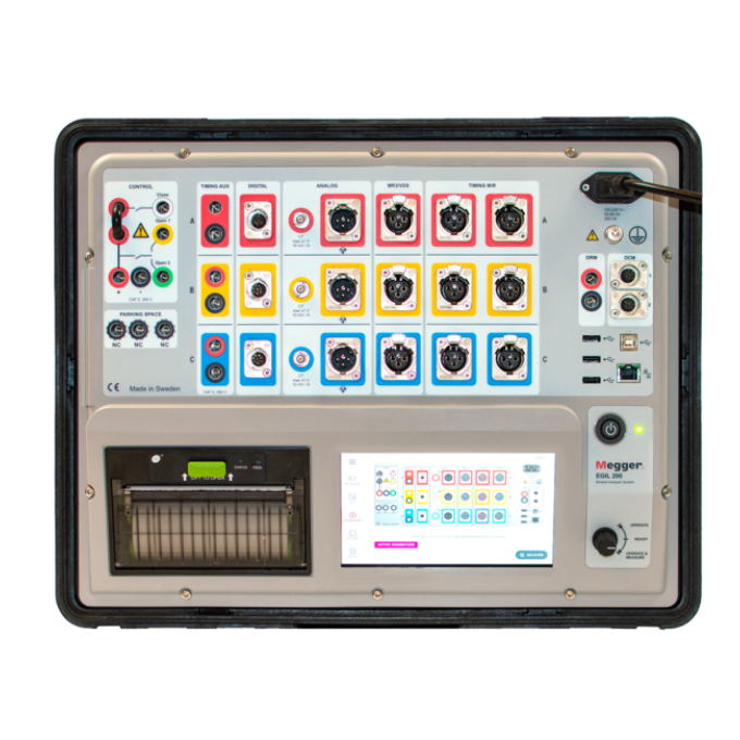
EGIL200 circuit breaker analyser


About the product
The EGIL200 circuit breaker analyser has been developed in response to demands for an affordable mid-range circuit breaker analyser that is fast and easy to use. The emphasis in the EGIL200’s development has been on ease of use, ensuring that the time spent setting up measurements is kept to a minimum. With the quick test mode, all relevant settings are on one screen, ready to select and begin testing.
Ideally suited for testing high and medium voltage circuit breakers in substation and industrial applications, this versatile instrument offers a wide range of functions. All recommended measurements specified in the IEEE C37 and IEC 62271 standards are included.
The EGIL200 is based on technology used in Megger’s market-leading EGIL and TM series of circuit breaker analysers, combining their ease of use with many other features that have made them so popular. These features include PIR contact timing and PIR resistance measurements, which are accurate even in noisy environments, thanks to their Active Interference Suppression technology.
Other key features of the EGIL200 include its one-click report generation ability. You can upload results to a PDF file or send them directly to an optional integrated printer. The EGIL200's robust construction makes it suitable for operation in even the most demanding on-site conditions.
Connection to the test object has also been streamlined, so you only need to connect the test leads once to perform all the following measurements or operations:
- Timing of main and PIR contacts
- Coil current analysis of close, open 1 and 2 coils
- Station voltage measurements
- Motion measurements
- Motor current measurement
- Minimum pickup voltage test for close, open 1, and open 2
The EGIL200 can be supplied in versions that are pre-configured for standard applications, such as medium voltage, high voltage, and dead-tank breaker testing, or in a fully customisable configuration that supports up to four breaks per phase and three analogue inputs.

Related products
Interpreting test results
A time and travel analysis verifies the correct operation of a circuit breaker. It assures that the breaker will be able to clear a fault in a matter of a few cycles. If the circuit breaker has been sitting for months or even years, it must be able to operate at a moment's notice. The best way to evaluate timing results is to compare the measured values against the manufacturer's specifications. The specifications should be in the circuit breaker's manual or on a commissioning checklist. Factory test reports are often delivered with the circuit breaker; they will have specifications or a baseline against which to compare.
If the manufacturer's specifications or baseline results are not available:
- an initial detailed measurement must be performed to generate a baseline. When a network has several of the same breakers, you can generate nominal values and a targeted range of specifications to compare against, adjusting any outliers as needed.
- the information below can be used as a general guideline but by no means applies to all circuit breakers.
Contact times are measured in milliseconds in modern circuit breakers. On older circuit breakers, they may be specified in cycles. The contacts that one evaluates include main contacts, resistor contacts, and auxiliary contacts. Five different operations or sequences are performed while timing: close, open, close-open, open-close (reclose), and open-close-open.
The main contacts are responsible for carrying the current when the circuit breaker is closed and, most importantly, extinguishing the arc and preventing a restrike when the circuit breaker opens to clear a fault. Pre-insertion resistor contacts dissipate any overvoltages that can occur upon closing higher voltage breakers attached to long transmission lines. Post-insertion resistors are used on older air blast circuit breakers to protect the main contacts during the opening operation. Both pre-insertion and post-insertion resistors are commonly referred to by the acronym PIR. The auxiliary contacts (AUX) are contacts within the control circuitry that tell the circuit breaker what state it is in and help control its operation.
The circuit breaker is rated in cycles, and this specifies how long the breaker will take to clear a fault. The open contact times will be less than the rated time of the circuit breaker because the open contact time is when the contacts actually part. In operation, once the contacts part, there is still an arc bridging the gap across the contacts that needs to be extinguished. The open contact time should be less than 1/2 to 2/3 of the rated interruption time of the circuit breaker, and the closing times are generally longer than the open times. The time difference between the three phases, known as pole spread or simultaneity between phases, should be less than 1/6 of a cycle for opening operations and less than 1/4 of a cycle for closing operations, according to both IEC62271-100 and IEEE C37.09. If the circuit breaker has multiple breaks within one phase, these should all operate almost simultaneously. If one contact operates faster than the others, then one break will have a significantly higher voltage on it compared to the others, causing a fault. A tolerance of less than 1/8 of a cycle is required by IEC, whereas IEEE allows 1/6 of a cycle for this intra-pole spread. Even with the limits specified by IEEE and IEC, the simultaneity of most circuit breakers is often specified at 2 ms or less. Contact bounce is also measured with the timing channels. Contact bounce is measured in time (ms) and can often appear on closing operations. Excessive bounce indicates that the spring pressure in the contacts is weakening.
Pre-insertion resistors (PIR) are used in conjunction with the main contacts on closing. The resistor is inserted first to dissipate overvoltages, and then the main contacts follow; afterward, the resistor contact is either shorted out or removed from the circuit. The main parameter to evaluate here is the resistor insertion time; this is how long the resistor contact is in the circuit before the main contacts close. Typical resistor insertion times are between half a cycle and a full cycle. If the main contact is faster than the resistor contact, the breaker is not functioning correctly.
Auxiliary (AUX) contacts are used to control the circuit breaker and let it know its state. The A contacts follow the state of the main contacts, i.e., if the breaker is open, the A contact is open, and if the breaker is closed, the A contact is closed. The B contacts follow the opposite state of the breaker, i.e., the B contact is closed when the breaker is open and vice versa. There are no generalised time limits for the difference between AUX contact and main contact operation. However, it is still important to understand and check their operation and compare them to previous results. The AUX contacts prevent the close and open coils from being energised for too long and burning out. AUX contacts can also control the contact dwell time, i.e., the amount of time the main contacts are closed on a close-open operation.
The motion curve gives you more information than any other measurement when performing time and travel analysis. It is vital to understand whether or not your circuit breaker is operating correctly. To measure motion, you connect a travel transducer to the circuit breaker, which measures the position of the mechanism or contacts as a function of time. The transducer will measure either an angular or linear distance. The angular measurements are often converted to a linear distance with a conversion constant or conversion table. A linear measurement can also be converted with a ratio as well. The goal is to translate the motion of the transducer into the actual motion of the contacts and determine the stroke of the main contacts. From the stroke, you can calculate various parameters. If no conversion constant or table is available, the stroke and related parameters can still be evaluated as is but may not match manufacturer specifications.
Velocity or speed is measured on both the opening and closing operations. The most critical parameter to measure on the circuit breaker is the velocity of the opening contacts. A high voltage breaker is designed to interrupt a specific short circuit current; this requires operating at a specific speed to build up an adequate cooling stream of air, oil, or gas, depending on the breaker type. This stream cools the electric arc sufficiently to interrupt the current at the next zero crossover. The velocity is calculated between two points on the motion curve. There are various ways to choose these speed calculation points, the most common being contact touch/separation and a time before/after or at distances below closed or open positions.

The travel curve above represents a close-open operation. The stroke of the contacts is measured from the ‘resting open’ position to the ‘resting closed’ position. When the circuit breaker closes, the contacts travel past the closed position; this is referred to as overtravel. After overtravel, the contacts may travel past the resting closed position (towards open); this is the rebound parameter. These parameters (i.e., stroke, overtravel, and rebound) are also measured on the open operation but are referenced to the ‘resting open’ position as opposed to the closed position.
The opening operation on the graph above shows both overtravel and rebound. The graph indicates where the contacts touch and separate. The distance from contact touch/separation to the resting closed position is referred to as wipe or penetration. The distance through which the breaker’s electric arc is extinguished is called the arcing zone. This is the position on the curve where you want to calculate the trip velocity referenced above. Since the open operations occur at high speeds, a dashpot is often employed to slow the mechanism down toward the end of the travel. The position where the dashpot is in effect is referred to as the damping zone. In many breakers, you can measure damping from the travel curve. Some breakers, however, may require a separate transducer hooked up to measure damping. You can measure damping on both open and close operations. Damping can have distance or time parameters associated with the curve.
The stroke of the circuit breaker is very small for vacuum circuit breakers, approximately 10 to 20 mm, and increases in the 100 to 200 mm range for SF6 circuit breakers, with longer strokes required for higher voltages. Older bulk oil circuit breakers can have stroke lengths above 500 mm. If comparing the stroke of two different circuit breakers, they should be within a few mm of each other as long as they are of the same type and use the same mechanism. If you can find no limits, you can compare the overtravel and rebound to the stroke of the breaker; they should be below about 5 % of the total stroke. Any excessive rebound or overtravel should be investigated to prevent further damage to the contacts and operating mechanism; a faulty dashpot is often the cause.
Measuring the operating voltage and coil current on a routine basis can help detect potential mechanical and/or electrical problems in the actuating coils well in advance of their emergence as actual faults. The main analysis focuses on the coil current trace; the control voltage trace will mirror the current curve in operation. The primary parameter for evaluating the voltage is the minimum voltage reached during the operation. The coil’s maximum current (if permitted to reach its highest value) is a direct function of the coil’s resistance and actuating voltage.
When you apply a voltage across a coil, the current curve first shows a straight transition that's rate of rise depends on the coil’s electrical characteristics and the supply voltage (points 1 to 2). When the coil armature (which actuates the latch on the operating mechanism’s energy package) starts to move, the electrical relationship changes, and the coil current drops (points 3 to 5). From this point on, the coil and latch system has completed its function to release the stored energy in the mechanism. When the armature hits its mechanical end position, the coil current rises to the current proportional to the coil voltage (points 5 to 8). The auxiliary contact then opens the circuit, and the coil current drops to zero with a current decay caused by the inductance in the circuit (points 8 to 9).

The peak value of the first lower current peak is related to the fully saturated coil current (max current), and this relationship gives an indication of the spread to the lowest tripping voltage. If the coil were to reach its maximum current before the armature and latch start to move, the breaker would not be tripped. If this peak changes with respect to previous measurements, the first thing to check is the control voltage and to what minimum value it reaches during operation. However, it is important to note that the relationship between the two current peaks varies, particularly with temperature. This also applies to the lowest tripping voltage. If the time between points 3 to 5 increases or the curve shifts up or down in this region, this indicates a faulty latch or a faulty coil. The most common cause is a lack of lubrication in the latch system; cleaning and lubricating the latch is advised.
WARNING: Follow the circuit breaker's safety protocols when performing any maintenance. At a minimum, the control power to the breaker must be off, and the mechanism energy needs to be discharged or blocked before maintenance.
If the latch system is lubricated correctly, the next step is to verify the resistance of the close and open coils to make sure they are correct and replace them as necessary.
The charts below indicate typical failure modes associated with time and travel measurements on high voltage circuit breakers and possible solutions to the problem.
WARNING: Follow the circuit breaker's safety protocols when performing any maintenance. At a minimum, the control power to the breaker must be off, and the mechanism energy needs to be discharged or blocked before maintenance.
| Close Time | Open Time | Damping Time | Charging Motor | Possible cause of failure condition |
|---|---|---|---|---|
| Faster/Slower | Normal | Normal | Normal | Change in characteristic of the closing system. Latching system is binding. |
| Faster | Normal | Normal | Normal | Spring charging system used for closing is defective. |
| Slower | Normal | Normal | Normal | Spring charging system used for closing is defective. |
| Normal | Slower | Normal | Normal | Change in characteristic of the closing system. Latching system is binding. |
| Faster | Slower | Normal/Slower | Normal/Slower | Reduced force exerted by opening springs. One of the opening springs is broken. |
| Slower | Slower | Normal/Slower | Normal/Slower | Increased friction throughout the entire breaker caused by (for example) corrosion in the linkage system. |
| Normal | Faster | Normal | Normal | Malfunctioning puffer system or extremely low SF6- pressure |
| Normal | Normal | Faster | Faster | Damaged opening damper. Not enough oil in the dashpot. |
| Normal | Normal | Slower | Slower | Damaged opening damper. Increased friction in the dashpot. |
| Tested parameter | Result |
|---|---|
| Coil current | Varies with coil resistance and control voltage. |
| Control voltage | Increased voltage drop indicates increased resistance of the coil supply cables. Must be measured in order to obtain traceability of coil current measurements and timing measurements. |
| Coil resistance | A change could indicate a burned coil or a short circuit between winding turns. Can be calculated from control voltage and peak current. |
| Armature stop time | Increased time indicates increased mechanical resistance in latch system or coil armature. |
| Armature start current | Increased current indicates increased mechanical resistance in coil armature. Gives an indication of the lowest operation voltage (coil pick up). |
| Max motor current | Varies with winding resistance, supply voltage and applied force. Start current not considered. |
| Motor voltage | Increased voltage drop indicates increased resistance in the motor supply cables. |
| Spring charge motor start time | Closing time of auxiliary contact for the spring charge motor. |
| Spring charge motor stop time | Increased time shows e.g. higher mechanical friction. |
Micro-ohm measurements, also commonly referred to as static resistance measurements (SRM) or as digital low resistance ohmmeter (DLRO) tests (sometimes also called Ducter™ tests), are performed on the circuit breaker while the contacts are closed to detect possible degradation or damage in the main contacts. If the resistance of the main contacts is too high, there will be excessive heating that can cause damage to the circuit breaker. Typical values are below 50 μΩ on distribution and transmission circuit breakers, whereas generator circuit breaker values are often below 10 μΩ. If the value is abnormally high, repeating the test several times or applying the current for 30 to 45 seconds may be needed to “burn in” the contacts; this will help to push through any oxidation or grease that may be on the contacts. The micro-ohm test results for all three phases should be within 50 % of each other, and any outlier should be examined. Always verify good connections and retest when values are high. IEC requires a test current of 50 A or greater, whereas IEEE requires 100 A or greater.


