DLRO100 series of digital low resistance micro-ohmmeters
About the product
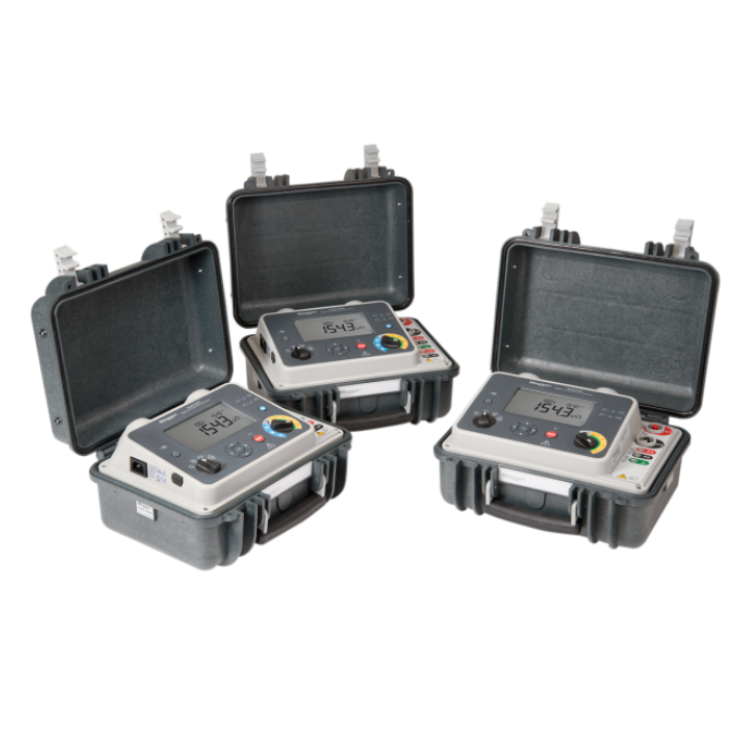
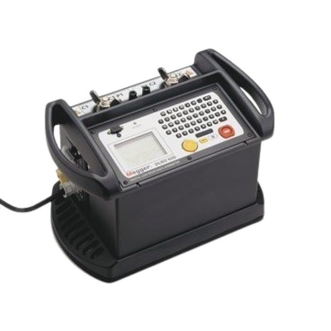
The DLRO100 series of digital low resistance micro-ohmmeters are portable, lightweight instruments that can deliver a test current of 100 A. They can be supplied with internal rechargeable Li-ion batteries that provide sufficient power for up to 200 manual/automatic tests on a single charge. This degree of autonomy makes it easy for you to perform high current low resistance testing in almost any location, including areas without access to a mains power supply.
To ensure dependable operation even in the most demanding environments, the DLRO100 instruments use novel circuitry that gives high noise immunity and guarantees stable readings. For physical protection, they feature enclosures with an IP54 ingress protection rating even when the lid is open and testing is in progress.
Operator safety in adverse conditions is assured by a CAT IV 600 V safety rating in line with IEC 61010. With an optional DC clamp, dual ground operation is also supported. DualGround™ greatly enhances safety when working in substations and similar environments by allowing tests to be carried out with both sides of the equipment under test grounded.
DLRO100 instruments have a wide range of applications, including checking the resistance of busbar and cable joints, measuring wire and cable resistance, and verifying lightning conductor bonding. They are also well suited for testing switchgear and circuit breakers during manufacture and in the field, and they offer a smooth DC output that is particularly valuable for circuit breaker tests.
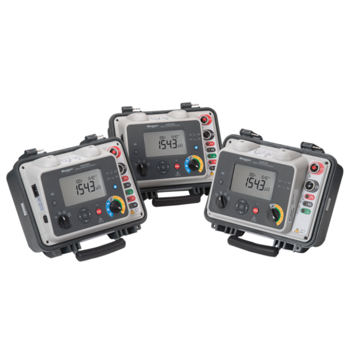
Instruments in the DLRO100 series have a measuring range of 0.1 µΩ to 1.999 Ω with a resolution of 0.1 µΩ. Results are shown on a large LCD panel and, depending on the model, can also be stored in a large capacity internal memory for later access via the display or downloading via a USB drive. Versions are also available with support for remote operation, Bluetooth connectivity, and asset/result tagging.
There are three main models in the series, each have battery and mains power supply:
- DLRO100EB is a battery and mains operated unit.
- DLRO100XB is a battery and mains operated unit. DualGround capability with optimal clamp and internal memory storage with USB drive download.
- DLRO100HB is a battery and mains operated unit. DualGround capability with optimal clamp and internal memory storage with USB drive download. Remote control, asset tagging and Bluetooth®.

Additional videos


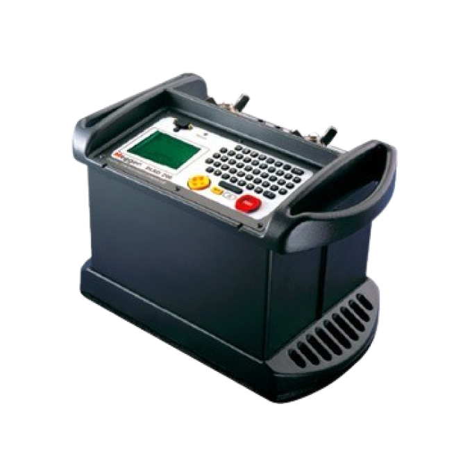
Related products
Using your product


