TTRU3 True three-phase transformer turns ratio tester
About the product
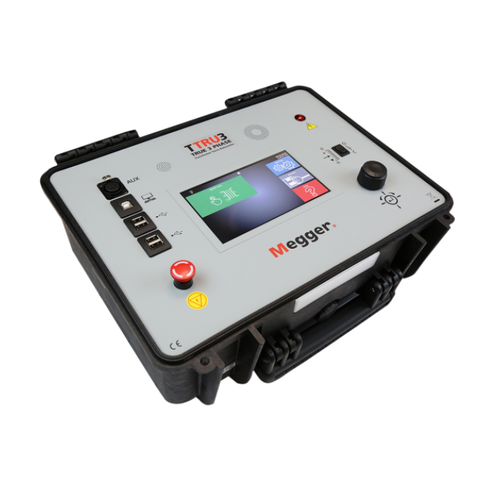
Megger’s TTRU3 transformer turns ratio tester is a revolutionary instrument designed to perform three-phase turns ratio measurements using step-up excitation (patented). A single three-phase lead-set connection is all that is required to complete three-phase tests in less than 10 seconds!
The TTRU3 is capable of three-phase excitation and can induce up to 250 V on the primary winding, overcoming the voltage dependence seen on larger transformers. The three-phase source also allows you to test phase shifting and zigzag transformers, and provides you with a guaranteed accuracy of ±0.05 % from -20 °C to +50 °C.
What’s more, the TTRU3 can be connected to a computer, enabling you to download results or control the instrument remotely. There is also an optional 2 inch printer for the instrument, enabling you to have a hard copy of your results if required.
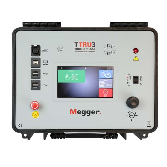
You can also configure test plans and store results directly on the TTRU3 using the built-in 7 inch (18 cm) daylight-viewable touch screen display. To generate reports, results can be downloaded in Excel, and PDF files can be saved to a USB drive.
Last but not least, it’s also the smallest and lightest three-phase test set on the market!

Additional videos


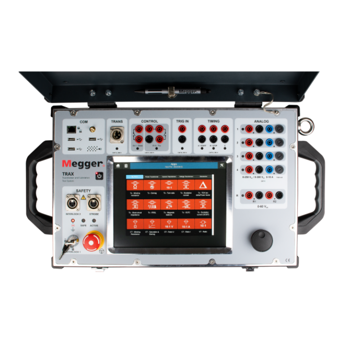
Related products

Using your product


