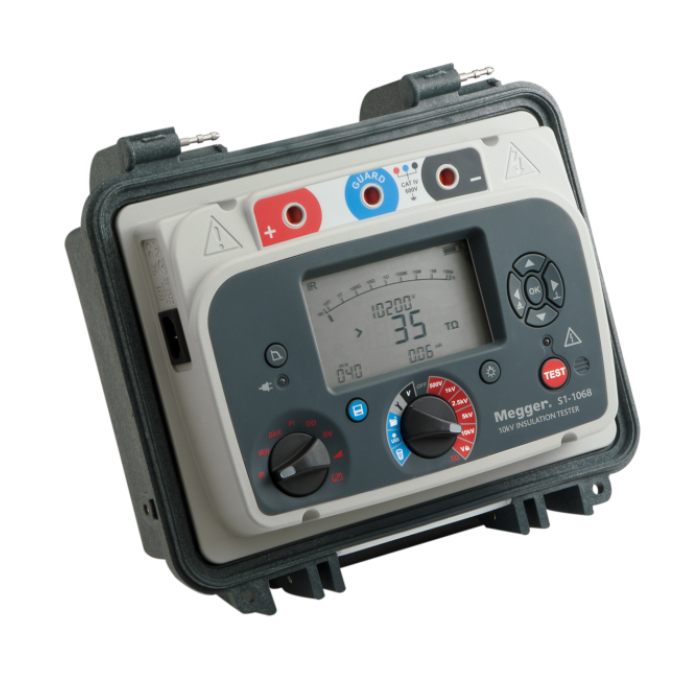
S1-568, S1-1068, and S1-1568 insulation resistance testers
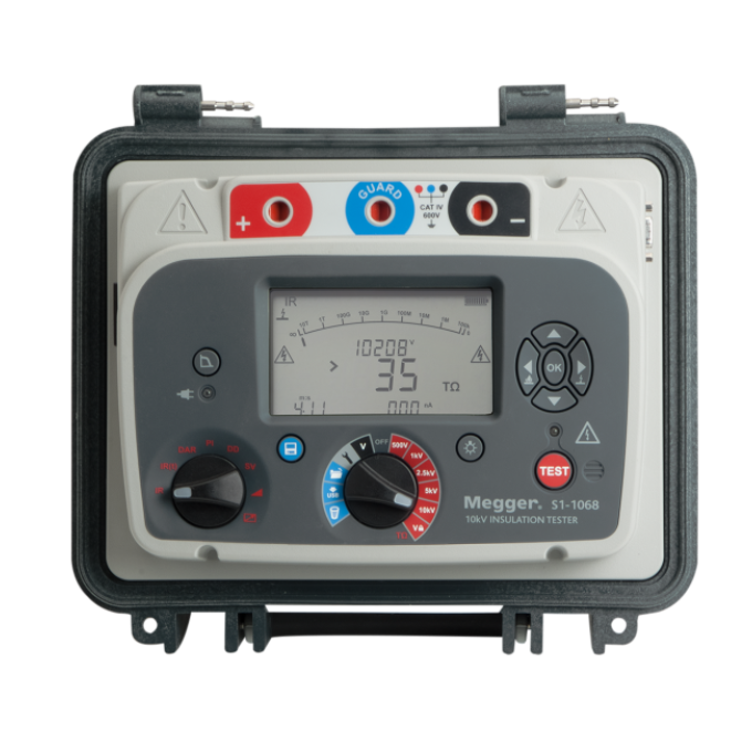
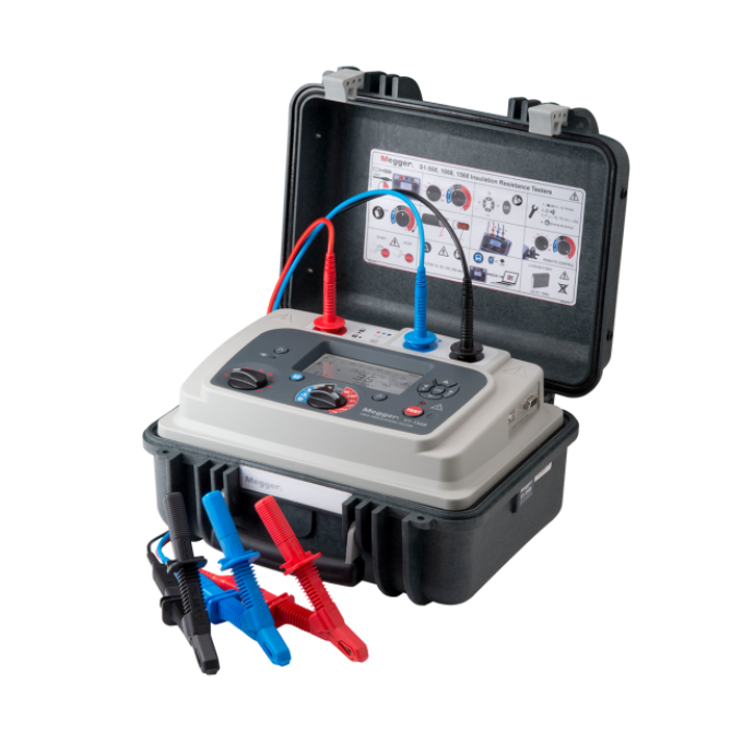
About the product
The S1-568, S1-1068, and S1-1568 insulation resistance testers from Megger come with class-leading noise rejection of 8 mA – twice that of most comparable instruments – and enhanced software filtering that has four user-selectable options. These DC insulation resistance testers come in 5 kV, 10 kV, and 15 kV and deliver dependable results in even the most severe of electrical environments, including high voltage transmission and distribution substations.
The performance of these groundbreaking instruments has been exhaustively proven in the laboratory and, more importantly, has been convincingly demonstrated in the field. Accurate and consistent results were, for example, obtained in a working 765 kV substation where no other insulation tester had been able to operate successfully.
Megger’s S1 series of insulation testers are available in three models:
- The S1-568 tests at up to 5 kV and can measure insulation resistance up to 15 TΩ
- The S1-1068 operates at up to 10 kV and measures up to 35 TΩ
- The S1-1568 has 15 kV capability and measures up to 35 TΩ
All models have a high short-circuit current of 6 mA to ensure rapid charging of items under test. The S1-568 and S1-1068 have a CAT IV 600 V safety rating, at altitudes up to 3,000 m, with the S1-1568 having CAT IV 1000 V to 4,000 m, in line with IEC 61010.
Other innovative features include the provision for remote control via a fully isolated USB port, which makes the instruments ideally suited for use in production environments, and internal storage for date- and time-stamped results. Stored results can be recalled to the display, downloaded via a Bluetooth wireless link, or accessed via the USB port.
To ensure that testing is never delayed through lack of power, these S1 insulation testers incorporate rapid-charge Li-ion batteries that give up to 6 hours of testing on a full charge for the 5 kV model and 4.5 hours for the 10 kV and 15 kV models. With just 30 minutes of charging from flat, the batteries give around one hour of testing time, and it’s also possible to operate the instrument from an AC power supply even if the battery is completely flat.
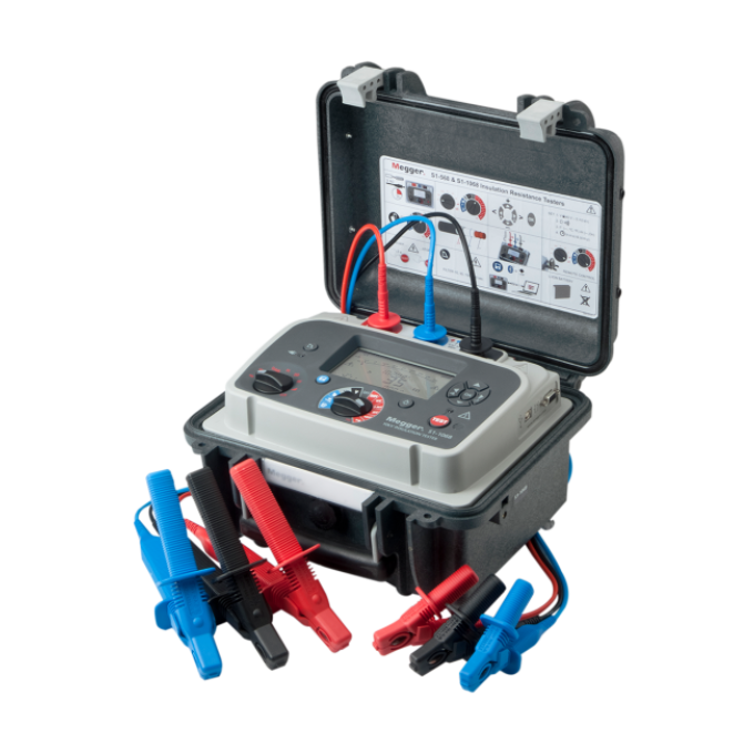
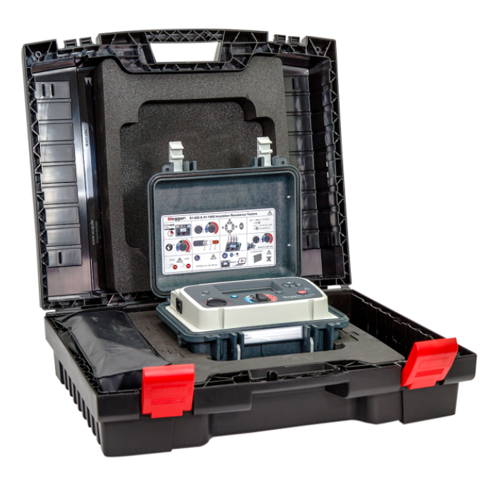
Compact and lightweight, the S1 insulation resistance testers feature a rugged dual-case design and, with the lid closed, they have an IP65 ingress protection rating. They offer timed insulation resistance (IR), dielectric absorption ratio (DAR), polarisation index (PI), dielectric discharge (DD), step voltage (SV) and ramp diagnostic tests, as well as a dedicated voltmeter function.
NEW
The patented PI predictor enables you to obtain 10 minute PI values in as little as 3 minutes! The new method starts to predict the final IR curve from 3 minutes into the test and as soon as the predictor is confident with the prediction, the test is stopped and the predicted value of the PI displayed. In most cases, this happens within 5 minutes, meaning the test time is typically halved!
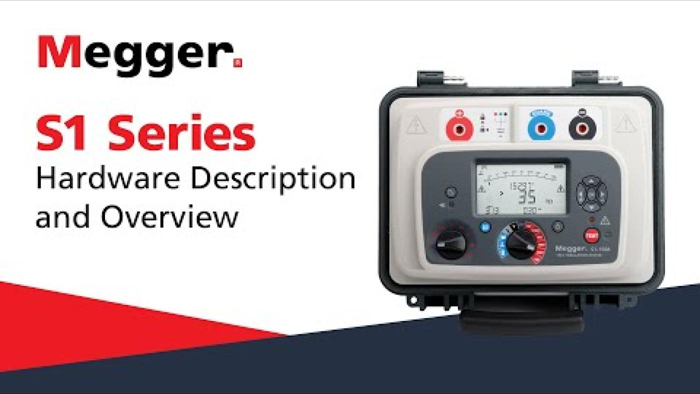
Additional videos
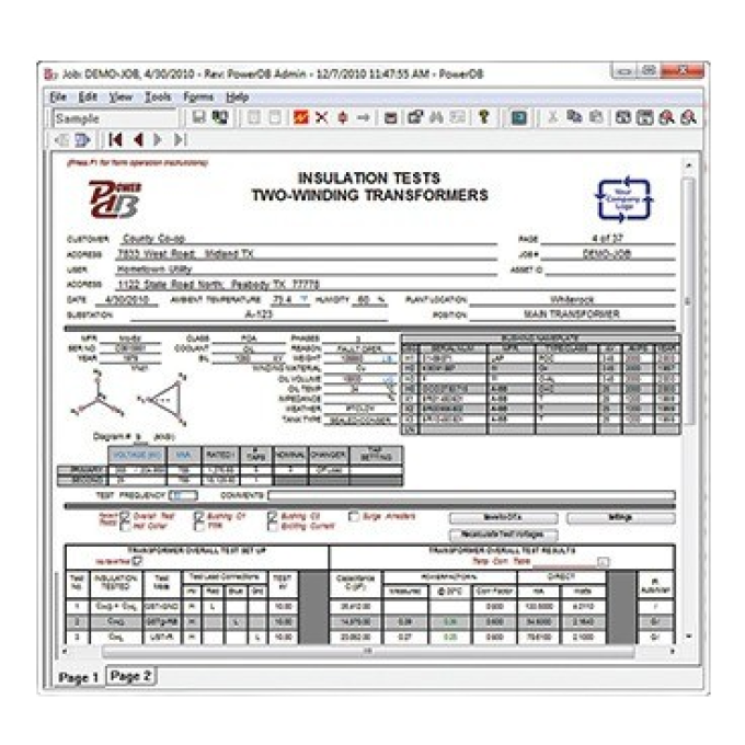
Related products
Using your product


