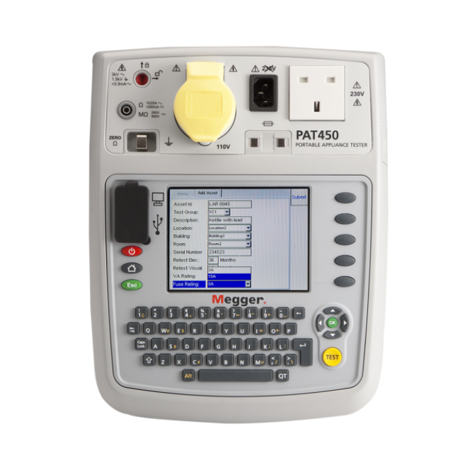
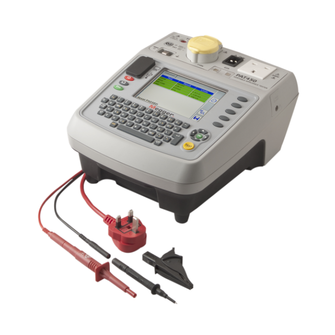
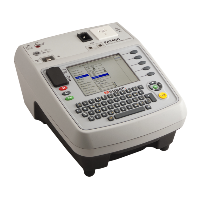
PAT450 portable appliance tester
About the product
Easy to use, light to carry, and featuring a convenient internal database for results storage, the PAT450 portable appliance tester is optimised for use by service organisations and equipment rental companies. Key benefits of the instrument include rapid start-up, instant restart after temporary disconnection when moving between test locations, and optional barcode support to aid in rapid asset identification.
These instruments offer both manual and automatic operation. When used in automatic mode, the test structure can readily be configured to suit specific requirements. This way, for example, a supervisor can predefine a test structure for a particular application and then be sure that all tests are performed exactly as required, irrespective of who carries out the testing work.
The efficient handling of test results is another important characteristic of these innovative instruments. They have an integral multi-user database with ten times the capacity of a typical downloading PAT tester. They use a flat data structure that enhances traceability and makes it easy to set up assets and find their associated data. Results can also be stored in test groups, and there is no limit to the length of the group names. These can be made descriptive and easy to understand, which is an important aid to testing efficiency.
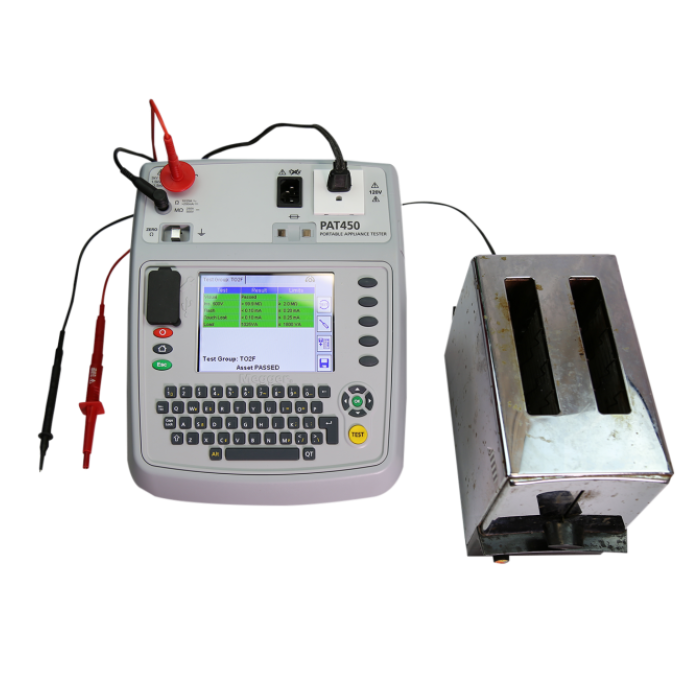
Tests offered by the PAT450 include earth continuity (bond testing), 250 V and 500 V insulation tests, alternative leakage tests, VA, anti-surge leads and power cords, testing 120 V assets, bond testing carried out at 10 A and 25 A as well as at 200 mA, plus 1.5 kV and 3 kV flash test functions.
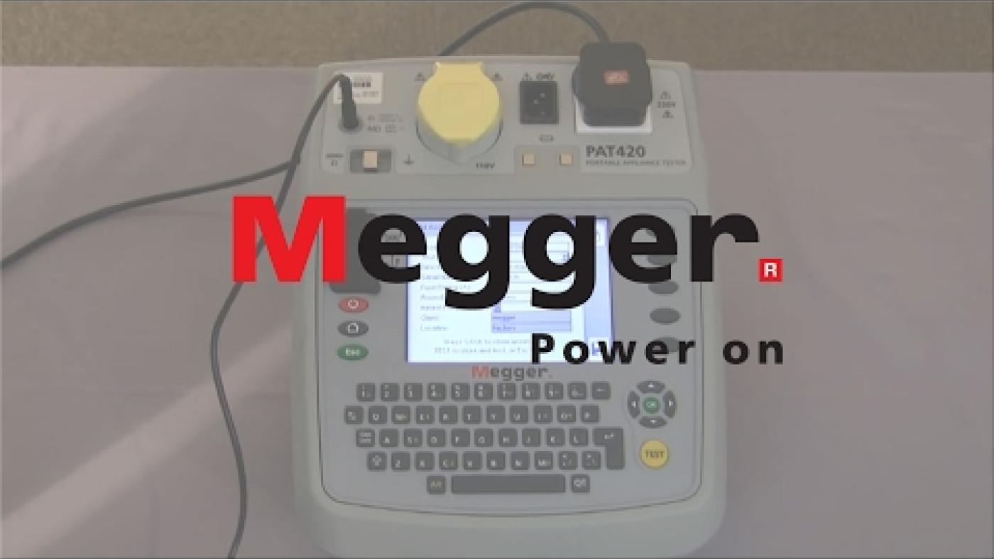
The PAT450 also has a large bright colour screen for clear test results and simple menu navigation. The menus have been simplified to make operation faster and more intuitive. Five soft keys give direct access to frequently used functions, making navigation through the menus even quicker and the tester even more productive, offering a greater return on investment.
Megger’s standard issue of these instruments includes a calibration certificate, printed quick start guide, complete user guide on CD, continuity/earth bond lead and probe, and a 13 A extension lead adapter, all presented in a convenient carrying case with an integral lead/document pouch.