OTS PB and OTS AF series of insulating oil test sets

About the product
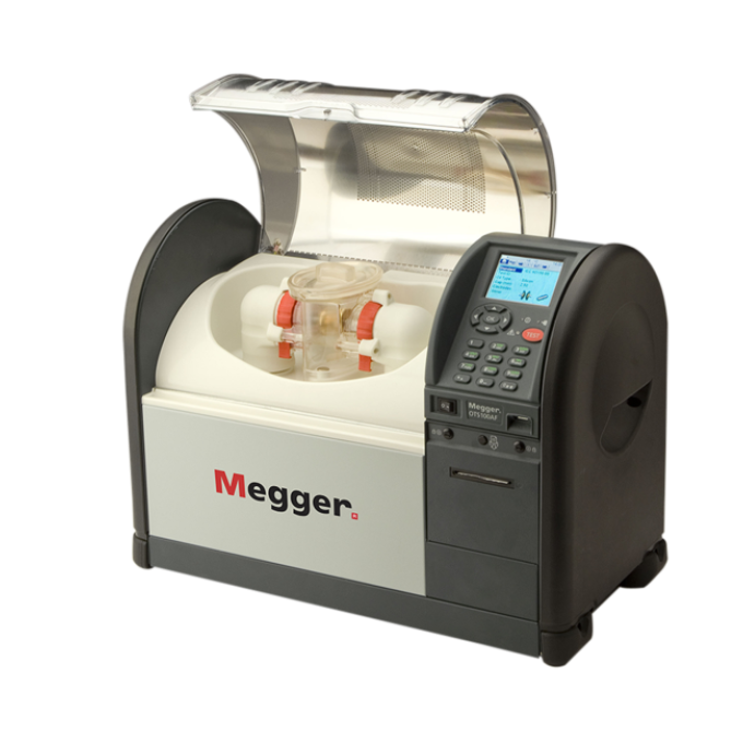
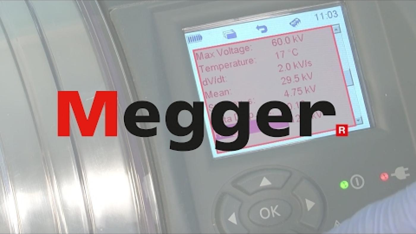
The OTS PB and OTS AF insulating oil test sets are a range of automatic oil test sets that perform accurate dielectric breakdown voltage tests on mineral, ester, and silicone insulating liquids. This critical test indicates the ability of a fluid to withstand electric stress. All models have precision, shatterproof test vessels that are easy to clean and provide repeatable results, whether used in the field or laboratory. They also have a transparent, shielded lid and a large test chamber, giving easy access to the test vessel and allowing you to see what is happening within it.
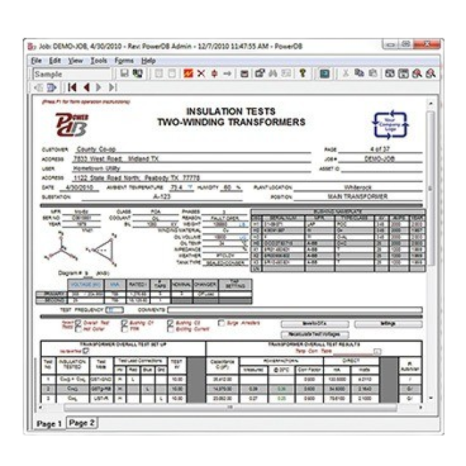
Test results are identified either by a serial number or asset ID and are time and date stamped. OTS units come with PowerDB Lite, Megger's asset and data management software, at no extra cost, giving you an excellent tool for downloading and printing results. The units have an internal printer so that you can have a hard copy of your results, if needed. In addition, the AF model includes a barcode scanner.
We have designed these test sets with your safety in mind. During a test, you can terminate the measurement at any time by pressing any button on the keyboard. Such a keyboard stroke will remove the high voltage immediately and abort the test. Additionally, the transparent lid provides ample visibility within the chamber yet is protected and electrically shielded by a screen with multiple links to the instrument's ground.
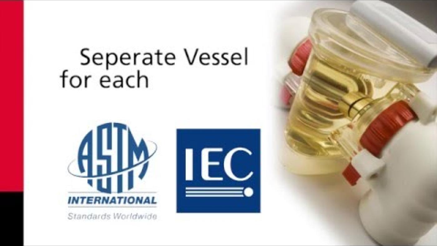
All existing test standards worldwide are pre-loaded in the instrument for convenient automatic operation. However, should a new test standard be accepted or a current standard amended, you can configure three custom tests to the new requirements. This flexibility enables you to continue testing for the short period over which Megger updates the test procedure files. New updated files are then downloaded by the user and installed into the test instrument via a USB drive.
OTS PB models
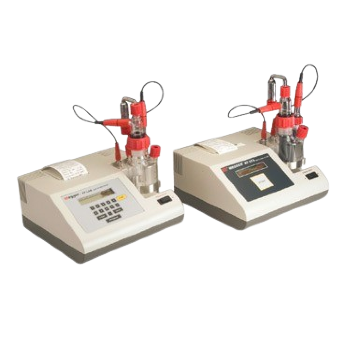
These 60 kV and 80 kV oil test sets are the smallest and the lightest on the market, with weights ranging from 16.8 kg to 20.8 kg, depending on the model configuration. These units can be mains powered or battery operated for additional flexibility in portable applications. All PBs are fitted with NiMH batteries and are also supplied with an internal 12 V DC charger and a vehicle adaptor cable as standard issue. The transport case and carry bag are optional accessories. The carry bag has pouches for the electrode accessory pack, leads, a quick user guide, and a paper roll.
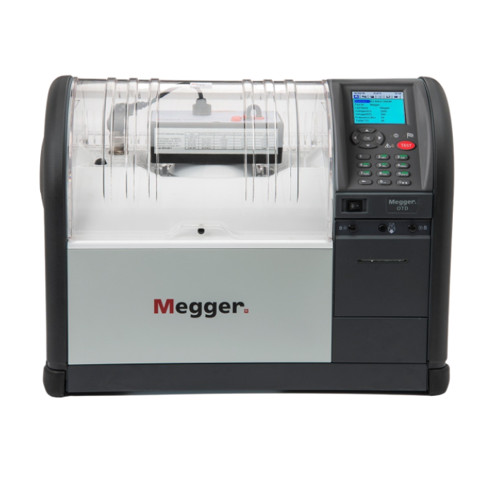
OTS AF models
These 60 kV, 80 kV, and 100 kV models have a much larger test chamber for even easier access and cleaning, which is particularly useful in a lab environment. They are fitted with a 12-key alphanumeric keypad to facilitate the entry of test IDs, file names, and notes. Alpha characters are entered by repetitively pressing a key. The AF models also can use a USB barcode reader to scan oil sample barcode labels, which is ideal for better integration within a laboratory.

Additional videos
Using your product


