MRCT relay and current transformer test set


About the product
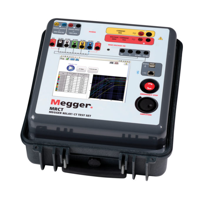
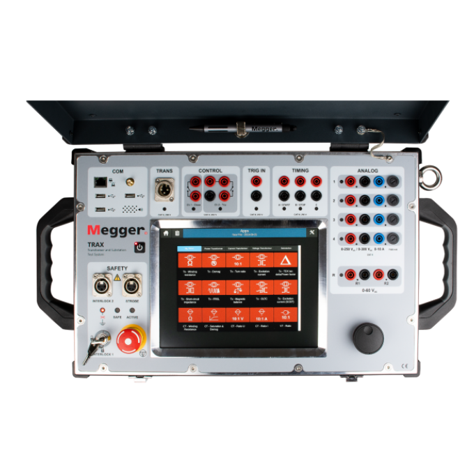
The MRCT relay and current transformer tester is a lightweight, robust, portable unit used to perform demagnetisation, ratio, saturation, winding resistance, polarity, phase deviation, and insulation tests on current transformers. The MRCT can be configured to include functionality for performing an excitation test on CTs using DC voltage, allowing measurement of knee points on CTs up to 30 kV. Additionally, the MRCT can be configured to test VTs and single phase relays.
The MRCT simplifies testing by automatically calculating ratio errors, saturation curves, and knee points. It also provides a microprocessor-controlled variable voltage and current output, as well as precision instrumentation, for automatically testing single and multi-ratio CTs, ultimately reducing testing time and increasing productivity.
What’s more, the MRCT will directly connect to multi ratio CT’s and perform all tests – saturation, ratio, polarity, winding resistance, and insulation – on all taps with the push of a button and without changing leads. When the test is finished, your report is generated automatically.
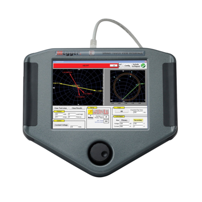
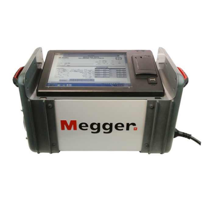
The MRCT can be controlled via Megger’s Smart Touch View Interface (STVI) controller. The STVI is a full colour, high resolution, LCD touch screen that allows you to perform manual and automatic testing quickly and easily via the manual test screen, as well as by using preset test routines. The large display enables you to easily read all pertinent data while the test is being performed, and gives you the ability to view the current transformer’s saturation curve.
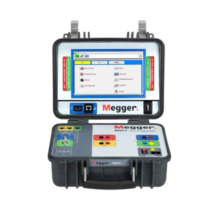
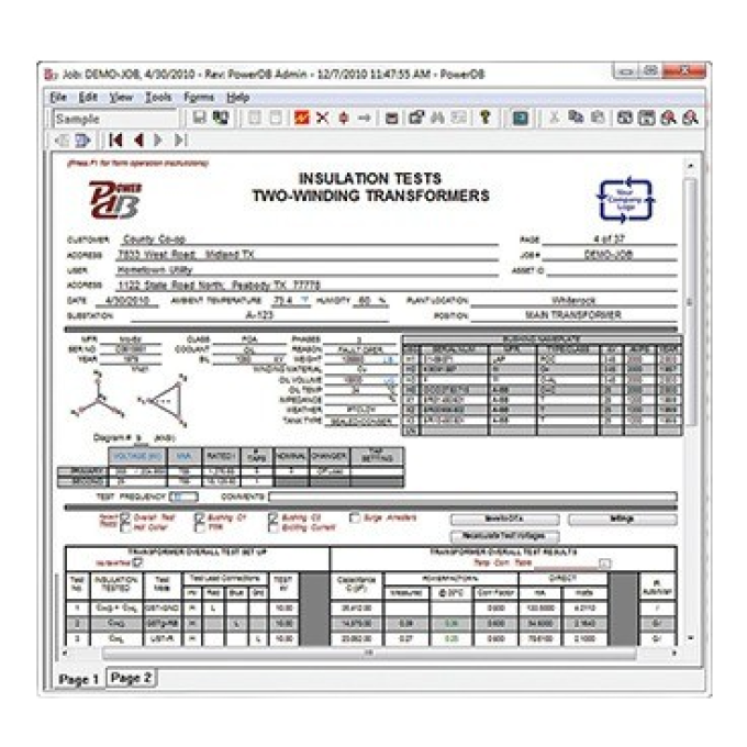
The unit can also be configured to come without a Megger STVI and can be controlled via a laptop with Megger’s PowerDB software.

Additional videos

Related products
Using your product


