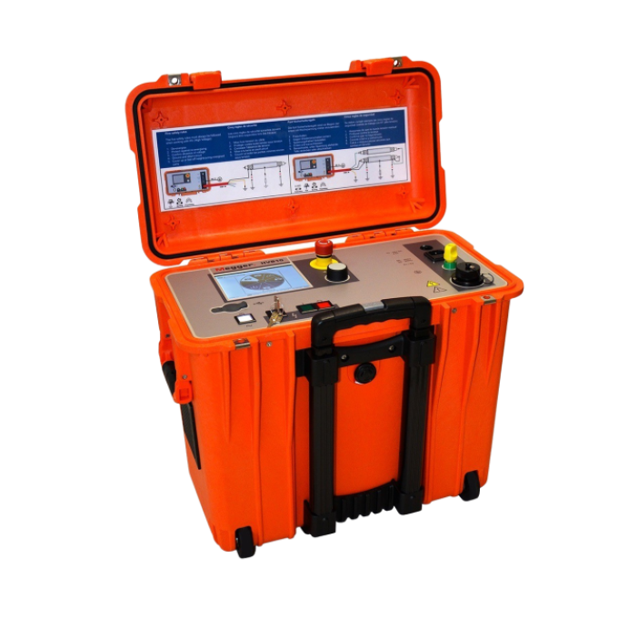
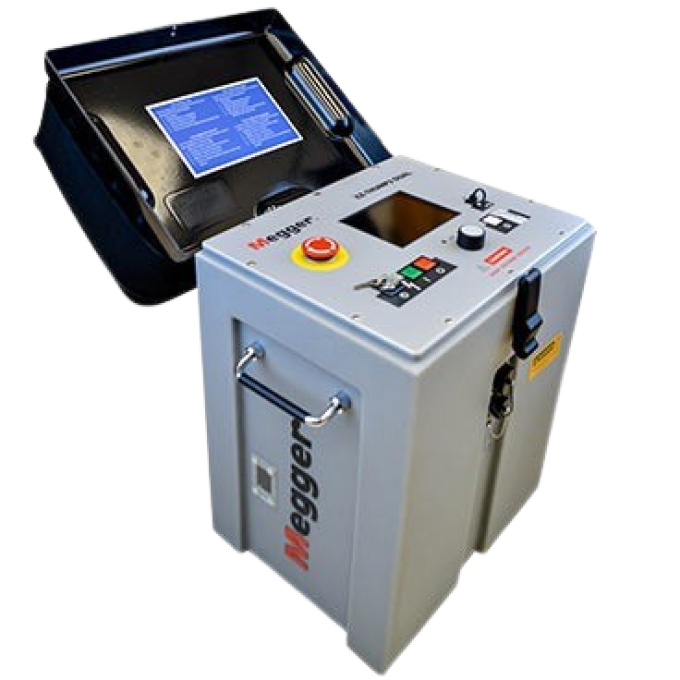
EZ-Thump 12 kV, model v3, cable fault location system

About the product
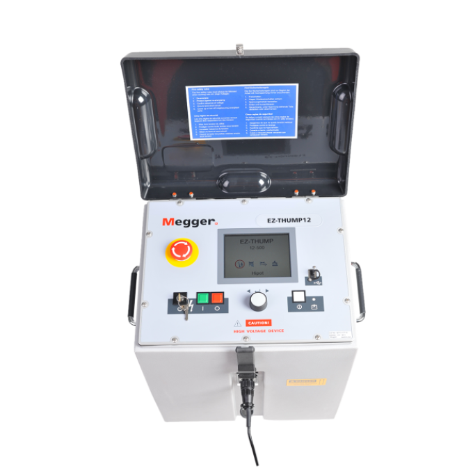
The EZ-Thump 12 kV, model v3, cable fault location system makes fault finding on underground MV power cables easier than ever! This all-in-one fault locator has been designed specifically to be readily transportable – it will fit into an average-sized car – and easy to operate, even for inexperienced users. The EZ-Thump 12 kV is an ideal choice for first responders and its extensive capabilities make it well-suited to more demanding applications.
The EZ-Thump 12 kV incorporates a single-stage capacitor surge discharge system that delivers 500 J at 12 kV. An integrated time-domain reflectometer (TDR) facilitates the pre-location of low resistance faults and, by using the Arc Reflection Method (ARM), high resistance faults. In addition, the EZ-Thump 12 kV can be used in conjunction with an acoustic/electromagnetic receiver, such as the DigiPhone 2, to pinpoint the precise location of faults. Sheath testing and sheath fault location are also supported.
The instrument includes advanced safety features as standard, such as the F-OHM system that automatically checks that earth/ground connections have been made correctly and, if detects a problem, will inhibit testing. It also has an emergency stop function and a key-switch safety interlock.
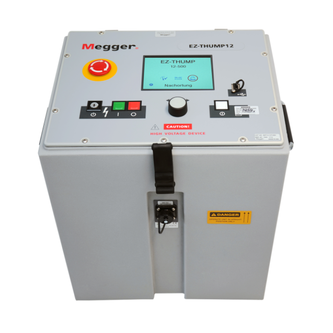
All of the instrument’s functions are controlled with a single rotary knob and the test results are shown on a bright colour display that is easy to read even in bright sunlight. No settings are needed when the instrument is used in automatic mode; users connect the test set to the cable and switch it on. The cable end and the fault location are then automatically detected and displayed. More experienced users can access expert mode to optimise results in particularly challenging applications.
Lightweight and exceptionally compact, the EZ-Thump 12 kV can be powered either from an AC mains supply or its internal rechargeable battery. These features mean you can use the EZ-Thump in any location, even where access is difficult and no mains supply is available. The internal battery is designed to have a long operating life, but when replacement eventually becomes necessary, you can do so in the field.

Additional videos


Related products


Using your product
Interpreting test results
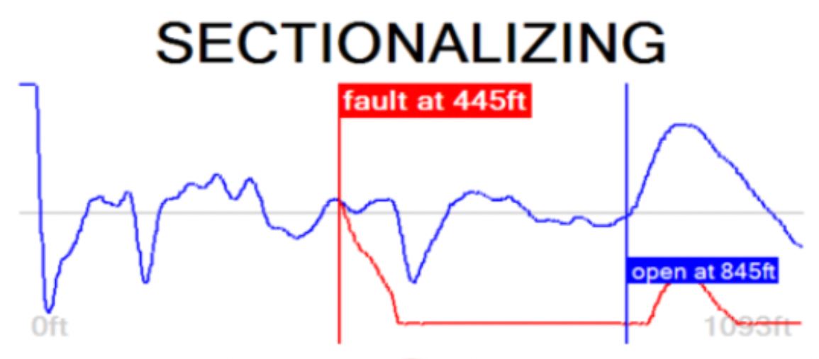
The sectionalising technique is used to troubleshoot single-phase medium voltage (MV) distribution loop circuits and identify a faulted section so that you can quickly switch it out, re-energise the rest of the circuit, and keep the power outage to a minimum. The advantage is that you can identify the faulted section working from one set-up point without going from transformer to transformer to either remove the fuses or to sand the elbows off at each transformer.
For this purpose, a low voltage (LV) reflection image is taken and scanned for impedance changes related to the cable end and the transformers. The latter ones indicate the location of the transformers. A second reflection image of a TDR pulse is taken while an electrical arc is ignited by a sudden discharge of the charged capacitor at the fault location.
By lying both traces on each other, the fault location (where the two traces diverge) is identified. The transformers' reflections provide landmarks to identify the faulted cable segment. You will switch out the faulty segment by pulling the elbows to the left and right sides of the fault. Service to all customers is provided by closing the normally open point within the distribution loop.
Determining the faulted section
An LV pulse is fed into the cable. The reflection image is processed by the transformer identification software. After a few seconds, the reference trace shows the distance to the cable end.
The red fault trace is shown in the display if a voltage breakdown occurs. The red fault marker is automatically set to the position where both traces diverge. The fault is referenced by the two closest transformers, identifying the cable section containing the fault.
Verifying a faulted cable section
The hi-pot test, within the context of sectionalising, is done to confirm that the section of cable identified as faulted during the preceding sectionalising procedure is actually faulted. Perform a hi-pot test after the identified cable section has been isolated at the two closest transformers.
Note: you must not perform a DC hi-pot test with the transformers still connected to the faulted cable section.
During the rise in voltage, the display will show the maximum charging current of the High Voltage Power Supply (HVPS) until the cable is fully charged. Once this occurs, the current will drop to the actual leakage current level. The insulation resistance is displayed. This scenario is observed if the cable has no insulation breakdown. If a flashover breakdown occurs, the high voltage will be shut off.
Depending on whether or not a breakdown takes place during the test, the display will present one of the following results:
- Breakdown at XX kV - A voltage breakdown occurred at the indicated test voltage.
- No flashover - The cable has withstood the applied DC test voltage. If possible, repeat the test with a higher voltage (do not exceed the maximum permissible voltage).
- Cable not chargeable - The test voltage could not charge the cable. This scenario is typically due to a short (fault) in the cable, creating maximum current output.
- Low resistance at XX kV - Due to the substantial leakage current level, the HV source cannot charge the cable beyond the indicated voltage value.
A hi-pot/breakdown test is used to test the dielectric strength of a cable under DC HV conditions and, in cases where the cable fails, it provides the breakdown voltage.
During the voltage rise, the display will show the maximum current of the HVPS until the cable is fully charged. Once this occurs, the current will drop to the actual leakage current level. The insulation resistance is displayed. This scenario is observed if the cable has no insulation breakdown. Otherwise, the high voltage will be shut off when the flashover/breakdown occurs.
Determining the dielectric strength of the cable
Depending on whether a breakdown takes place during the test,
the display will present one of the following results:
- Breakdown at XX kV - A voltage breakdown took place at the indicated test voltage, meaning there was a flashover at the fault.
- No flashover - The cable has withstood the applied DC test voltage. In this case, no current will be indicated. If required, repeat the test with a higher voltage (do not exceed the maximum permissible voltage).
- Cable not chargeable - The test voltage could not charge the cable. This scenario typically occurs when a short circuit condition is present in the cable (zero voltage and max current).
- Low resistance at XX kV XX MΩ - The HV source cannot charge the cable beyond the indicated voltage value due to a substantial leakage current level; this suggests the presence of a very low resistance fault (some voltage and high current). You must not interpret the voltage indication as the flashover voltage. Given the high leakage current, it is merely the voltage that the HVPS can build.
The EZ-Thump applies the widely approved and well-known ARM to pre-locate a high resistance MV cable fault.
Locating the fault is accomplished by comparing a reflection image (impedance) taken with an LV pulse (reference trace) to a reflection image (impedance) taken when an arc, ignited by the sudden discharge of the charged capacitor, was present at the fault location (fault trace). With this method, the two measured traces diverge at the position where the arc causes a negative reflection (impedance change) of the TDR pulse, indicating the fault location.
You can use the thumping mode to pinpoint a high resistance fault between a phase conductor and the neutral conductor of an MV cable; between two phase conductors of a 'belted' MV cable; between two phase conductors of an LV cable, or between the phase conductor and earth/ground of an LV cable.
The EZ-THUMP provides an internal surge generator to continuously feed high voltage pulses into the defective cable, producing a flashover (arcing) at the fault position. You can pinpoint the fault using a magnetic/acoustic detector (such as the digiPHONE+) for best results or with a simple acoustic detector with distinct and well understood limitations. The criterion for pinpointing with a simple acoustic detector is the greatest loudness of the flashover noise at the fault location or, in the case of a magnetic/acoustic measurement, the smallest propagation time difference between the speed of light and speed of sound, where it is not the loudest sound, but the first after receiving magnetic signal. The latter is more accurate and can be used in all high resistance fault situations and even for pinpointing faults in conduits.
The insulation of any high or medium voltage shielded power cable is protected from water ingress by a jacket made from XLPE or PVC. The sheath test checks if the jacket's integrity has been compromised, typically during installation.
With a sheath test, you can test the dielectric strength of the cable jacket by applying a DC voltage of up to 5 kV between the cable shield (concentric neutral) and ground. Any leakage indicates a fault in the jacket. During the voltage rise, the display will show the maximum current of the HVPS until the cable is fully charged. Once this occurs, the current will drop to the leakage current level. The insulation resistance is then displayed. This scenario is observed if the cable has no insulation breakdown. Otherwise, the high voltage will be shut off when the flashover/breakdown occurs.
Depending on whether a breakdown takes place during the test, the display will present one of the following results:
- Breakdown at XX kV - A voltage breakdown occurred at the indicated test voltage.
- No flashover - The cable jacket has withstood the applied DC test voltage. The test can be repeated using the menu item.
- Cable not chargeable - The test voltage could not charge the cable shield. This scenario typically occurs when a short circuit condition is present in the circuit (fault in the jacket).
- Low resistance at XX kV XX MΩ - The HV source cannot charge the cable beyond the indicated voltage value due to a substantial leakage current level; this suggests the presence of a very low resistance fault (some voltage and high current). You must not interpret the voltage indication as the flashover voltage. Given the high leakage current, it is merely the voltage that the HVPS can build.
You should follow a failed sheath test with fault locating the sheath fault (in direct buried cables). The test method is based on the step voltage method (earth gradient method). You can perform this with any EZ-Thump serving as an HV pulse generator (limited to 5 kV). An additional receiver is required to read the strength and polarity of the earth gradient voltage (e.g., Megger ESG-NT or Digiphone+2 ) to pinpoint the sheath fault.
When approaching the fault position, the step voltage increases quickly and decreases to a zero reading directly over the fault and then will swing to a substantial voltage of the opposite polarity when going past the fault.


