Support for the 
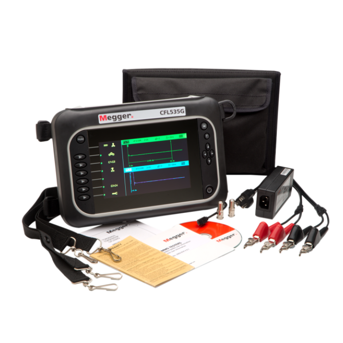
CFL535G dual-channel time domain reflectometer

Service your product
Log in to register your product, book a repair or calibration.
Troubleshooting
If your CFL535G won’t power on, it is likely because the battery is not charged. Plug in the charger, charge for six hours and then proceed with testing.
These symptoms indicate that there is a battery malfunction. Please get in touch with your local Megger dealer for a replacement battery.
These are signs that the charger is not functioning. Please get in touch with your local Megger dealer for a replacement charger.
Someone may have set the instrument’s standby time too low. Access the user settings and increase the standby time.
The display of the CFL535G may not be visible because its colour settings are incorrect. Access the user settings and change the colours. Conversely, the instrument may be in “power save” mode - press the standby button to return to the display.
An inaccurate fault distance result is likely due to an incorrect velocity factor (VF) setting. Check the VF value for the cable under test and change the settings.
If the cable velocity factor is unknown, test a known cable length to determine the velocity factor.
When this is the case, the CFL535G is set to “automatic”. Press the escape button and change to “manual”.
When the dual input function is selected, ‘ticking’ is expected due to the relays switching input.
When ticking occurs on a single input test, there is an incorrect connection to the cable under test. Therefore, the end of the cable is not determined, so the CFL535G cannot reach the max range. Check all connections and perform the test again.
You have chosen the wrong range. Press the up navigation button from the main screen to extend the range.
You have set your gain too low. Select and change the gain with the navigation buttons while in “manual” mode.
You have set your gain too high. Select and change gain with the navigation buttons while in “manual” mode.
Check that you have plugged the test leads into the correct channel.
Interpreting test results
The cursor lines on the CFL535G allow the user to identify disturbances at strategic points to determine distances and positions of potential faults on the trace.
Common fault traces include:
User guides and documents
FAQs
Splits and re-splits are where one conductor, each of two different pairs, is switched somewhere along the cable length. The split appears as an upward blip, and the re-split as downward. A TDR used in traditional mode looking for impedance discontinuity can find this split. A challenge is that this discontinuity is small, making the reflection difficult to identify. If the re-split is close, the pattern is more pronounced and easier to recognise. If the re-split is a distance away, attenuation reduces its size and makes identification difficult. The CFL535G in XTALK mode significantly enhances the reflection and makes finding distant re-splits easier. In XTALK mode, the split appears as a downward blip, and the re-split as upward.
Telephone customers first complain of static or no dial tone. Cable customers complain of snowy reception. High-resistance series faults or intermittent connectors usually cause these symptoms. They can be difficult to trace because they come and go with loop current on the line. Finding these with a TDR can be difficult. With a CFL535G, first, disconnect at the protector on the subscriber end. Connect a butt set, turn the speaker on and listen to the line. Turn the butt set to mute and dial the silent termination. Doing so eliminates noise picked up by the microphone of the butt set. Connect the CFL test probe leads to the pair under test. Keep the butt set connected with the silent termination. Switch on the TDR and initiate “Intermittent Fault Locate Mode”. Wait for the fault to occur, usually within 5 to 10 minutes.
A TDR will find water in a cable, but it is often difficult to determine how widespread the moisture contamination is. Moisture lowers impedance. In filled cable, moisture cannot migrate and so appears as a point problem. In air-core or pulp cable, moisture can migrate, so it may be important to trace the length of the contamination. You can facilitate such tracing by testing from both ends. Measurements up to the start of the ingress can be accurate. Beyond that point, the trace tends to flatten out, and specific distances can be erroneous due to changes in VoIP. In a twisted pair cable, each pair usually becomes impregnated at different points. Hence, you can use the range of these points to determine the length of the water contamination. Water can enter through a pinhole in the outer plastic insulator and then migrate within the cable. Each pair may indicate ingress at different points. But the water may have migrated away from the break in the outer sheath. It may be necessary to visually inspect the cable to prevent the problem from recurring.
Focus on the drop line from the metre to the transformer. With aerial cables, focus on the section that is not visible. With buried cables, focus on the cable between the meter and the manhole. Pulling the meter to gain access to the cables may be necessary. Connect the TDR test leads to the phases. Be sure the model you use has an internal blocking filter to protect the operator and instrument. Connect to the phases first. Next, test between the neutral on each of the phases. A difference in waveforms may indicate the presence of a tap.
When upgrading to ISDN, HDSL, or ADSL, you must remove load coils. A load coil may look like the open end of the cable. However, two criteria can help distinguish a load coil from a cable's open end. A load coil generally has a more rounded appearance than an open. And load coil spacing appears at regular intervals, such as 3000 feet, 6000 feet, etc. A TDR signal cannot pass through a load coil, so all you will see is the distance to the first one. Remove that and retest. If you now see the same reflection at twice the distance, it is reasonably certain that these are load coils.
A common problem is confusing the connections of transmit antenna cables with receive antenna cables. These can become mixed up during installation, and such misconnections must be sorted out and reconnected. Turn the noise filter off and connect the TDR to the transmission cable with an antenna in place. Zoom in and study the waveform. You will see a noisy waveform. The RF signal from the antenna will show up on the TDR baseline as noise. A high-gain antenna, such as the receive antenna, will have more signal amplitude than the relatively low-gain transmit antenna. This difference in amplitude provides for the distinction between receive and transmit antennas. If it is necessary to see the actual waveform of the cable, turn the instrument on and activate the noise filter.