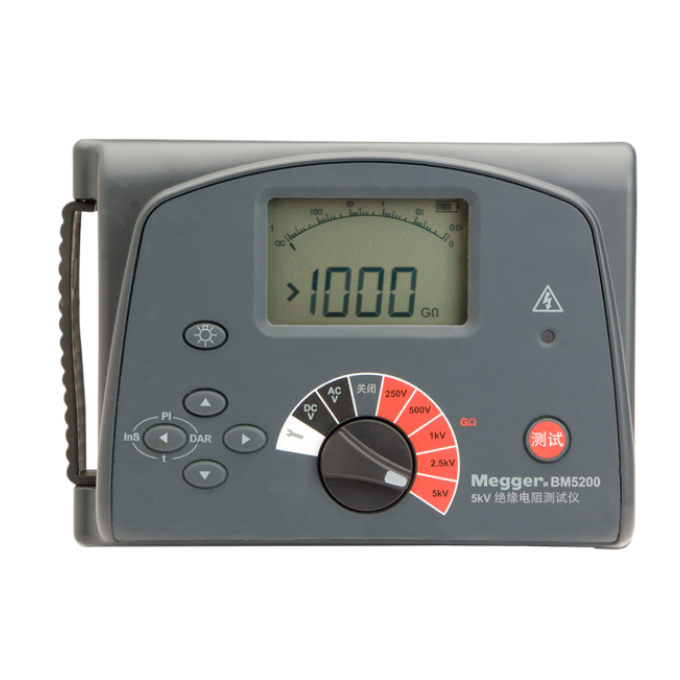
BM5200 5 kV insulation resistance tester
About the product
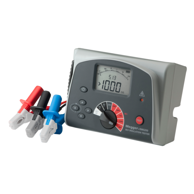
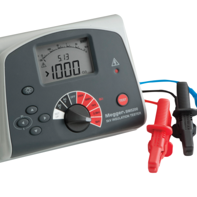
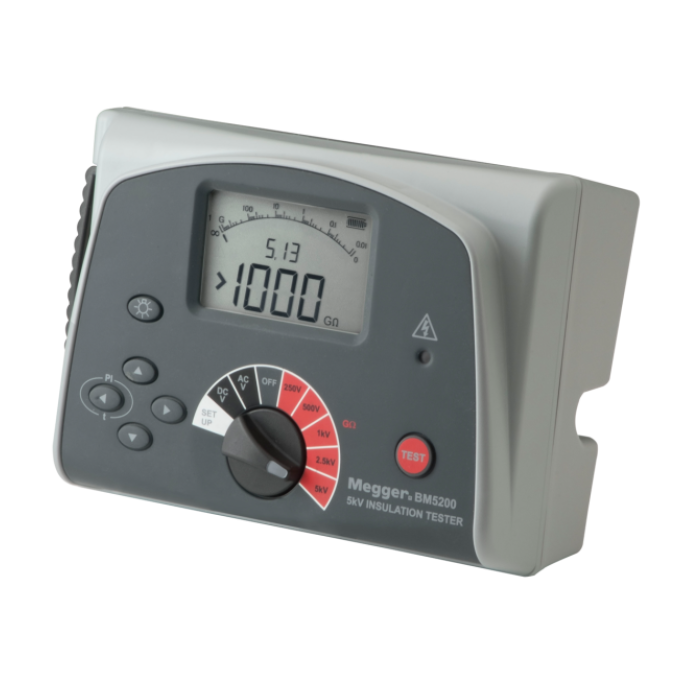
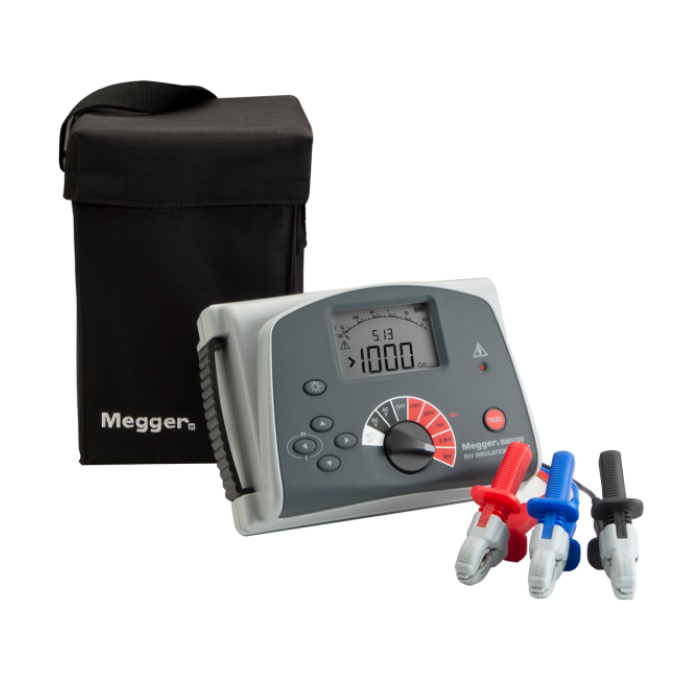
The BM5200 5 kV insulation resistance tester has been designed for high voltage insulation resistance testing in the maintenance and servicing of cables, rotating plant machinery, transformers, switchgear, and industrial applications.
With the BM5200, you can perform DC insulation tests at 250 V, 500 V, 1000 V, 2500 V, and 5000 V. Its insulation resistance measuring range is from 100 k Ω to 1000 G Ω. What’s more, it provides an automatic discharge for capacitive circuits under test and displays decaying voltage.
The instrument is not only battery powered, but it also comes with both a digital and an analogue arc display. It also uses a guard terminal to increase the accuracy of its results by minimising the effects of surface leakage that can lead to measurement errors.