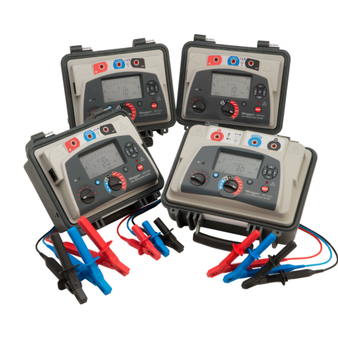
MIT515, MIT525, MIT1025, and MIT1525 insulation resistance testers
À propos du produit
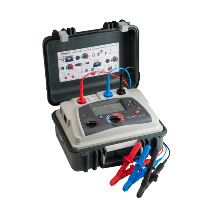
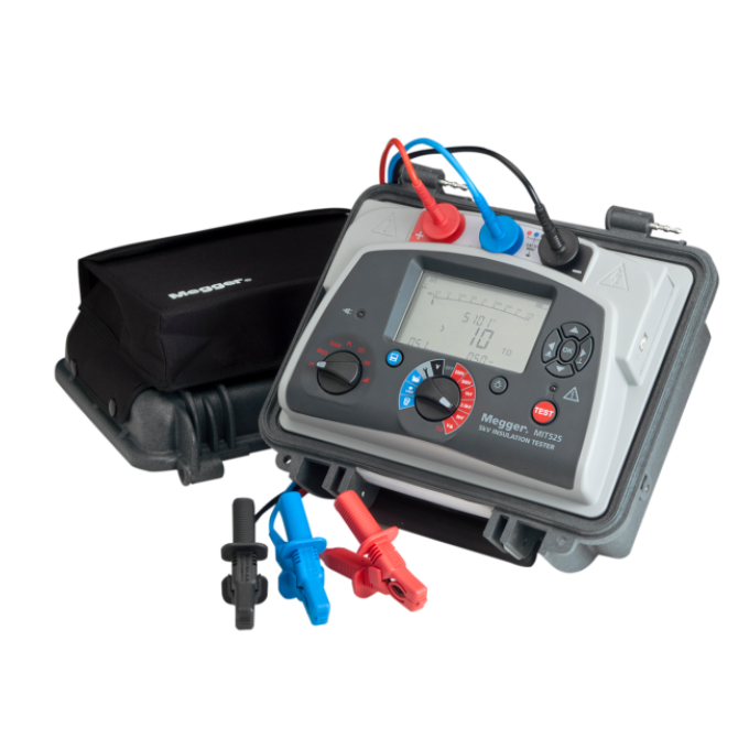
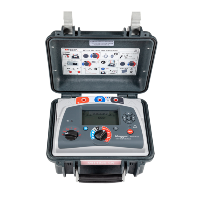
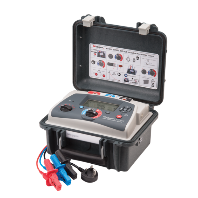
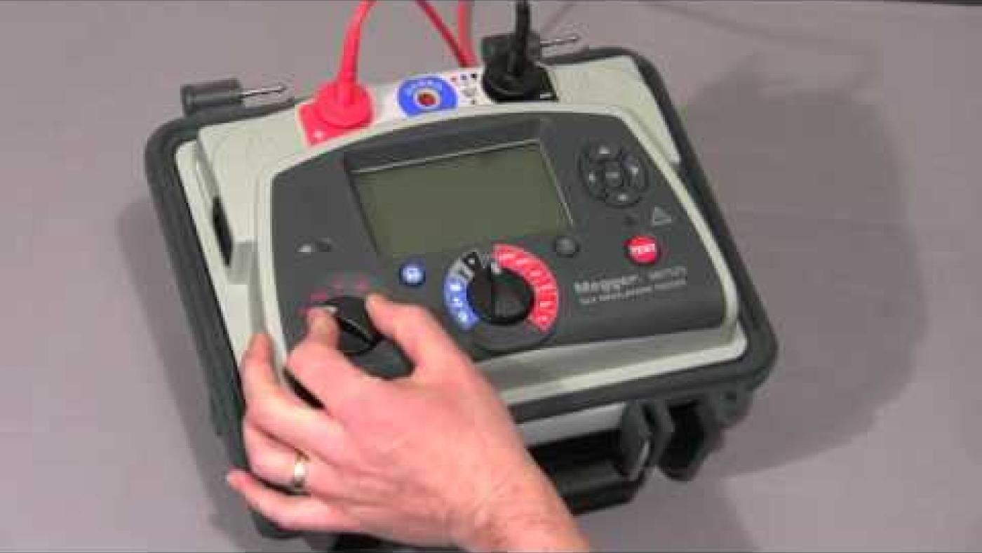
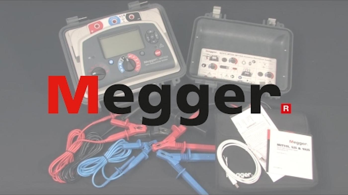
The MIT515, MIT525, MIT1025, and MIT1525 insulation resistance testers are compact, light 5 to 15 kV units for the diagnostic testing and maintenance of high voltage electrical equipment. They are ideal for original equipment manufacturers (OEMs) and industrial companies.
The MIT series has a full suite of test modes as well as on-board memory and the ability to stream data/download data to a PC/laptop. They also have rapid-charge batteries and operate from an AC source if the batteries are dead. Rapid charge batteries enable >60 minutes of testing after a 30-minute charge.
The MIT range includes:
- MIT515: 5 kV with IRT and DAR, but with no memory
- MIT525: 5 kV IRT with all test modes, including a ramp test plus advanced memory functions with recall to screen, RTC for time/date stamp of results, and USB drive to PC/PowerDB
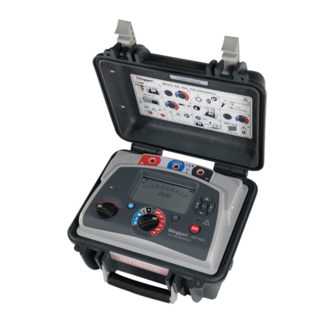
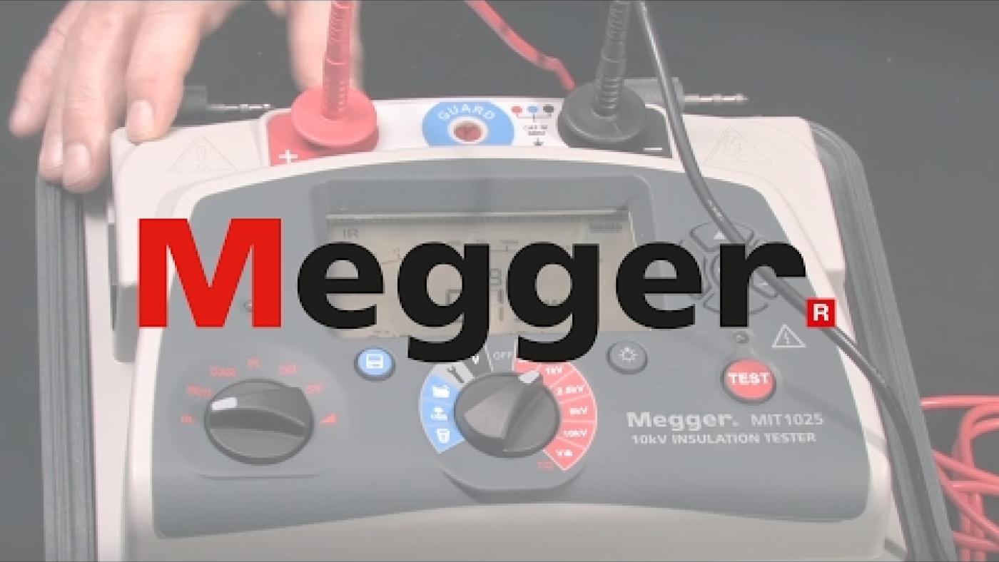
- MIT1025: 10 kV IRT with all test modes, including a ramp test plus advanced memory functions with recall to screen, RTC for time/date stamp of results, and USB cable interface to PC/PowerDB
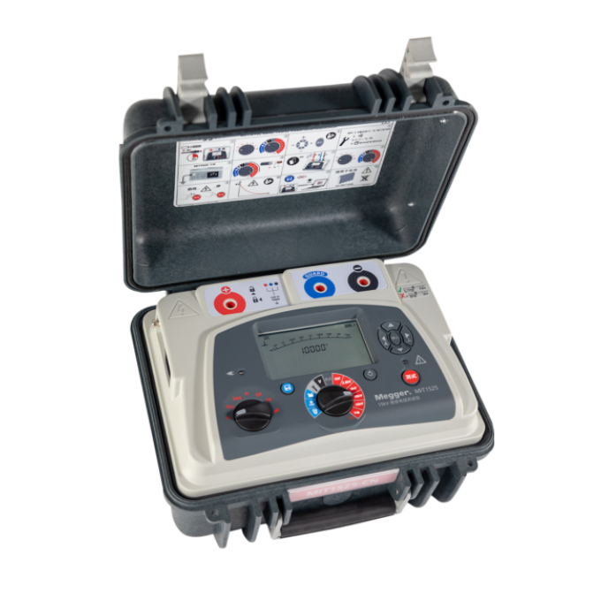
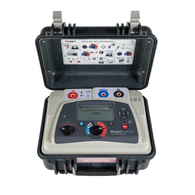
- MIT1525: 15 kV IRT with all test modes, including a ramp test plus advanced memory functions with recall to screen, RTC for time/date.
The MIT1525 is at the top of the range, and it performs insulation resistance tests up to 15 kV with a 30 TΩ maximum resistance and an accuracy of ±5 % from 1 MΩ up to 3 TΩ.
Safety rated to CAT IV, all these units are smaller and lighter than their predecessors, making them even easier to carry and store.
NEW
The patented PI predictor enables you to obtain 10 minute PI values in as little as 3 minutes! The new method starts to predict the final IR curve from 3 minutes into the test and as soon as the predictor is confident with the prediction, the test is stopped and the predicted value of the PI displayed. In most cases, this happens within 5 minutes, meaning the test time is typically halved!
Vidéos supplémentaires

Produits connexes
Utilisation de votre produit


