SMRT46 and 46D multi-phase relay testers
Constant power output for better test results
The current amplifier delivers maximum compliance voltage to the load constantly during the test
Higher output current for all instantaneous overcurrent relays
Up to 32 Amps at 200 VA RMS continuous, or up to 60 Amps at 300 VA RMS for short durations. Three SMRTs can be paralleled to give 180 Amps at 900 VA RMS
IEC 61850 testing capability
Ethernet port can be used for connecting to the IEC 61850 substation bus or process bus for testing IEC 61850 devices
Perform end-to-end tests
Using the AVTS software’s dynamic control with a GPS satellite receiver, you can perform satellite-synchronised end-to-end dynamic or transient tests
Über das Produkt
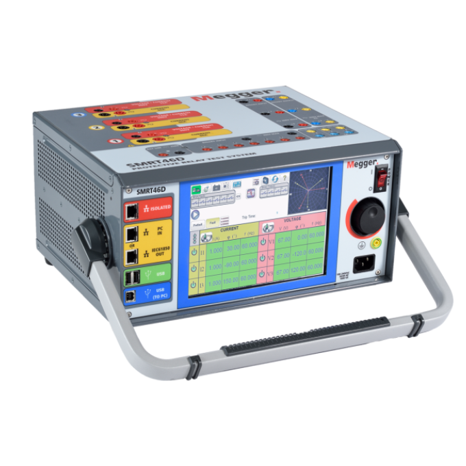
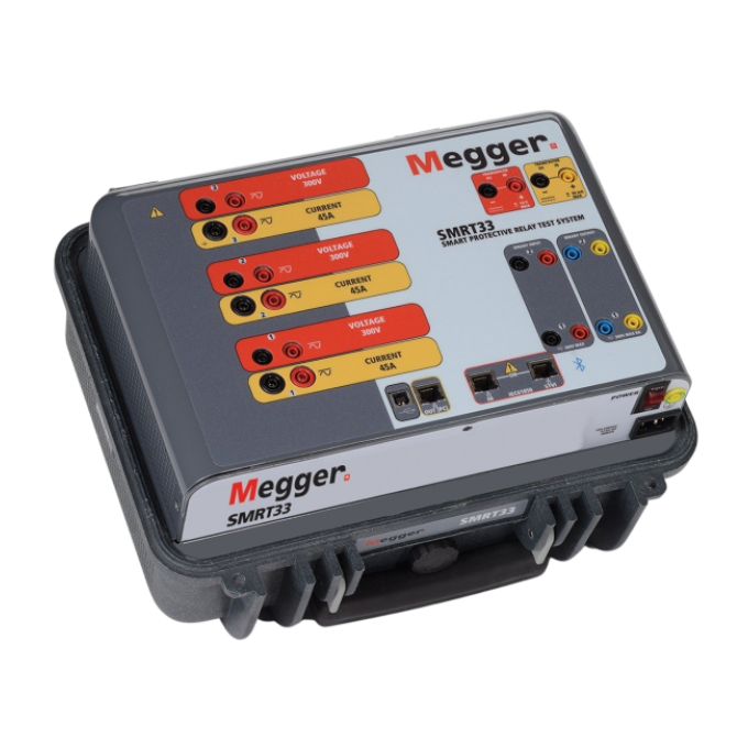
The SMRT46 and 46D are multipurpose, lightweight, field portable test sets capable of testing various electromechanical, solid-state and microprocessor-based protective relays, motor overload relays, and similar protective devices.
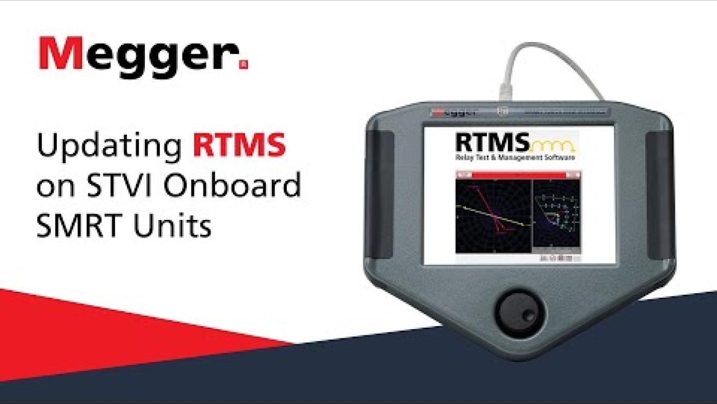
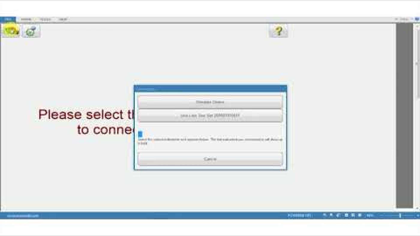
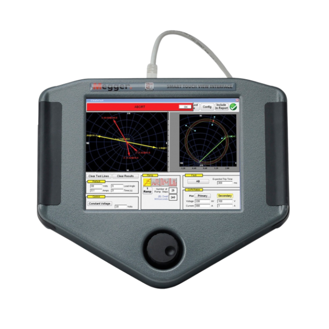
You can manually control the SMRT46 and 46D test systems with Megger’s new Smart Touch View Interface (STVI). The SMRT46D has this feature built-in, enabling it to be used without a PC via an intuitive, high-resolution graphic touch screen, whereas the SMRT46 requires an external device.
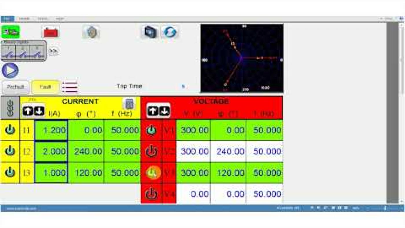
The STVI is a controller loaded with Megger’s user interface software. Its large, full colour, high resolution, TFT LCD touch screen allows you to perform manual, steady-state, and dynamic testing quickly and easily using the manual test screen and built-in preset test routines for the most popular relays. Menu screens and touch screen function buttons are provided to quickly and easily select the desired test function. Test results can be saved to the STVI for download to a USB drive to transfer or print test reports.
Both instruments can be placed under full computer control via the Advanced Visual Testing Software (AVTS) or the RTMS running on a PC. AVTS is a Microsoft Windows XP/Vista/7/8/10 compatible software program designed to manage all aspects of protective relay testing using the Megger SMRT46.
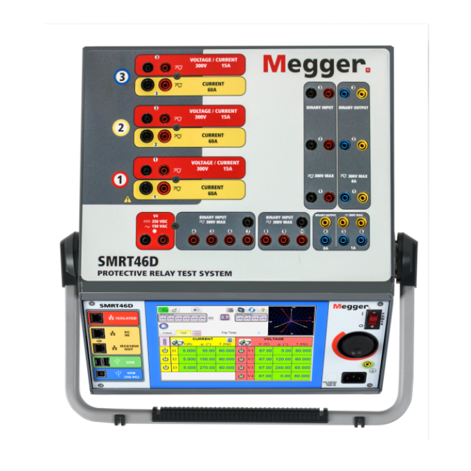
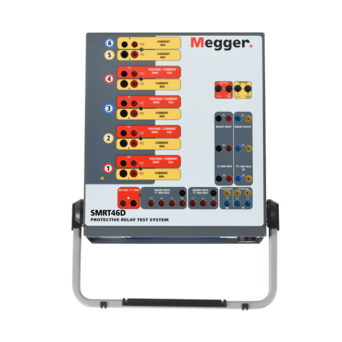
The test system may also be customised by adding the number of voltage-current modules, called VIGEN modules, needed for specific test applications with a maximum of three channels. For example, the SMRT46 or SMRT46D with three VIGEN Modules provides complete three-phase testing of three-phase impedance, directional power, negative sequence overcurrent and other devices that require a three-phase four-wire wye-connected source. The fourth voltage channel provides an AC reference/synchronising/polarising voltage, or a DC battery simulator voltage source.
Technische Daten
- Automation
- Yes
- IEC 61850 testing capability
- Yes
- Convertible channels
- Yes
- Output frequency range
- DC - 1000 Hz, Transient signals: DC - 10 kHz, Aux DC
Verwandte Produkte
Fehlerbehebung
The most common form of communication used with the SMRT units is via ethernet. If you cannot establish communication, it is important to check that RTMS is enabled in the local firewall. Sometimes the antivirus installed on the computer will block ethernet communications to the SMRT. Another possible reason for the failure to communicate is that the IP addresses of the unit and the PC are not on the same subnet. Changing the IP address of the SMRT or the PC to be on the other’s subnet will fix the issue. We recommend configuring the SMRT in DHCP mode so that it takes an IP address in the same subnet as the PC connected to it. If the SMRT’s IP address has been set to a fixed value, it is possible to force the unit into DHCP mode using RTMS.
When serial communication, such as USB or Bluetooth, fails, the culprit is usually the port number used, which you can check on the device manager.
The Bluetooth pairing code is a standard default of 0000 (four zeroes).
Things to check:
- In the SMRT/RTMS
- Is the binary input on the SMRT configured as wet or dry contact? Does it correspond with the relay’s binary output’s operation?
- Is the type of operation properly selected? i.e. “Normally Closed” or “Normally Open” contact?
- Is the trip input properly selected? Sometimes the SMRT is connected to the proper output on the relay, but RTMS is expecting the trip input on a different channel.
- In the relay:
- Is the test signal used adequate for the test? For example, if a 51 pickup is being tested, the timing signal cannot be used to trip and vice versa.
- Is the trip properly assigned to the output on the relay?
- Is there any condition blocking the trip inside the relay?
- Is the proper polarising signal being used?
In the SMRT46 or SMRT46D units, the battery simulator doubles as the fourth voltage channel. For this reason, seeing the four voltage channels on the home screen indicates that the battery simulator is not activated. If that’s the case, go into the configuration screen by clicking on the “gearbox” button and click on the “Use Last V as Battery” button. When you return to the home screen, you’ll see that you no longer have a fourth voltage channel available, and the battery icon has been enabled.
Auswertung der Prüfergebnisse
Relay testing can range from basic tests, like verifying the relay detects the right overcurrent conditions, to extremely complicated tests verifying a plethora of operating conditions, and even synchronisation between different relays. With that in mind, the text below provides frequently asked questions that are focussed on results interpretation and verification that the results measured are viable.
For each test, the RTMS report provides a visual indication of the status of the results. Results status may be either not performed, incomplete, failed, or passed.
The RTMS evaluates the report and provides a pass or fail status based on whether all the tests have passed (or not). All the tests must have a passed status for the report to have a passed overall status. Each test is time-stamped, indicating the date and time when the test was performed.
Each test is evaluated using criteria specific to the test. For some tests, you can set the tolerances directly in the report. In contrast, for others, they must be set inside the test form before performing the test. The specific values for the tolerances used are your responsibility. You can find these in the relay's manual or select tolerances from the local test procedures.
The overcurrent curves are built around a pickup value, a time dial, and a curve type. They are sometimes affected by the election of an electromechanical reset. Those are the first things to check if the times are not correct.
If the curve followed by the results is like the target relay curve, but the times are lower than those of the target curve, then perhaps the issue is that we have selected a higher time dial than that of the relay. Another reason for lower times could be the choice of pickup value. If, for the test, we choose a pickup value higher than that of the relay, then the times will also be lower.
If the form of the results curve is different, then the type of the curve could be the reason. If there is an electromechanical reset or if we are testing an electromechanical relay, we must provide enough time between consecutive test points. This extra time will allow the relay to fully reset or return to the zero position before injecting current again.
Sometimes an instantaneous element is also inadvertently tripping on the same contact. This situation should be easy enough to verify since the trip times will be very low. In this case, testing for multiples below the pickup of the instantaneous will fix the issue.
Bedienerhandbücher und Dokumente
Software und Firmware
SMRT
SMRT Firmware files - For SV capability there is a two app firmware available, one for 50 Hz systems and one for 60 Hz systems
PowerDB Software
Onboard install files are for FREJA, RTMS, SMRT and STVI local device installation. PC install is for remote operation of a wide range of Megger test instruments including FREJA, RTMS, SMRT, STVI and BITE5.