SVERKER900 relay and substation test system
Über das Produkt
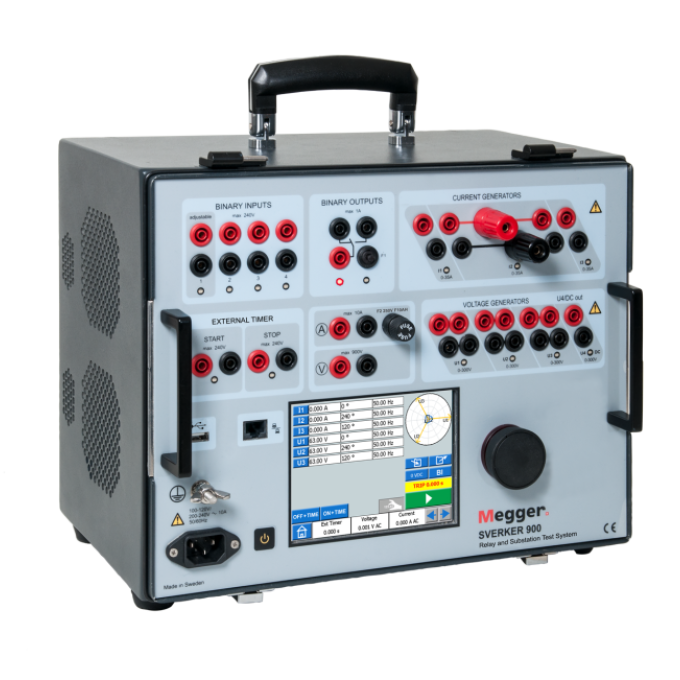
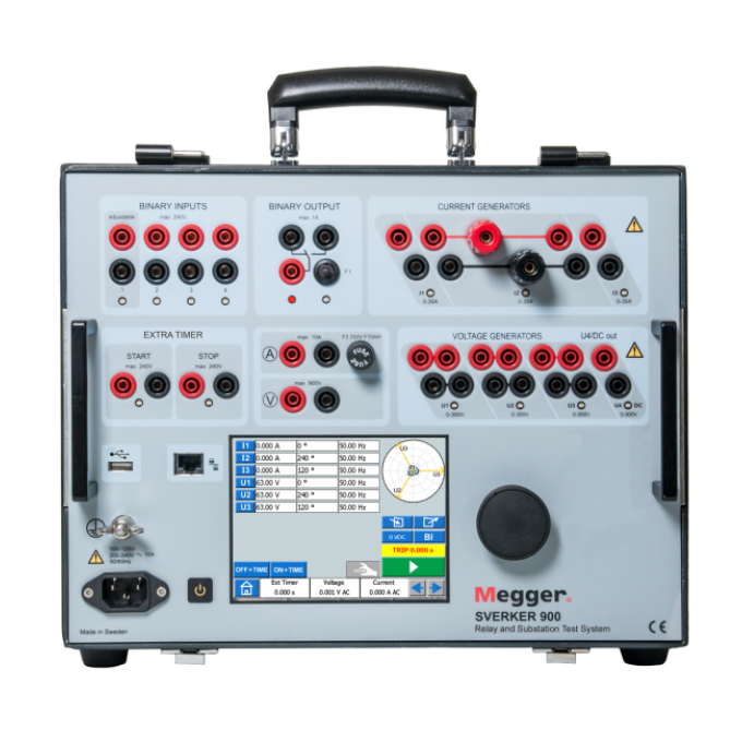
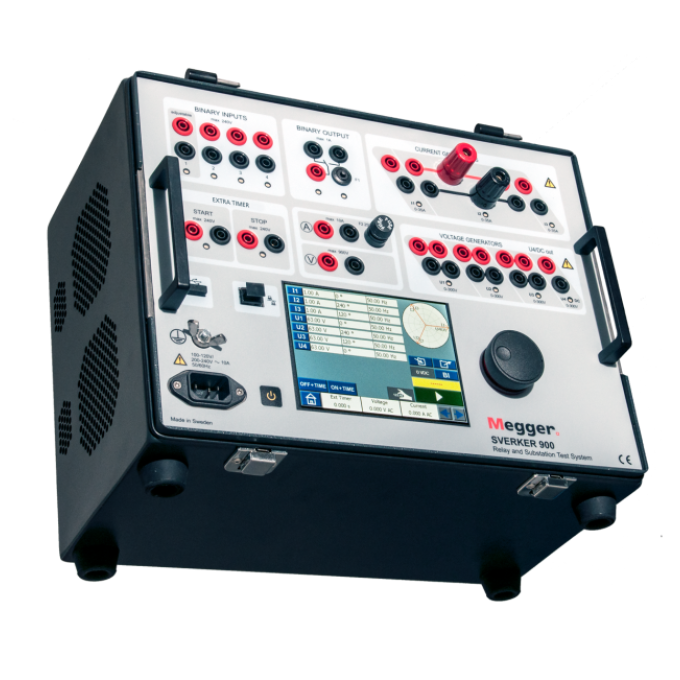
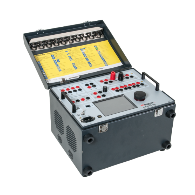
The SVERKER900 relay and substation test system is the engineer’s ultimate toolbox, addressing the increasing need for three-phase testing in electrical distribution substations, renewable power generation stations, and industrial applications. It has a powerful combination of current and voltage sources and a range of measurement possibilities.
The SVERKER900 is specifically designed for basic, manual three-phase secondary testing of protection devices. In addition, you can perform various primary tests as the current and voltage sources can be connected in series and/or parallel to give you up to 105 A AC or 900 V AC output.
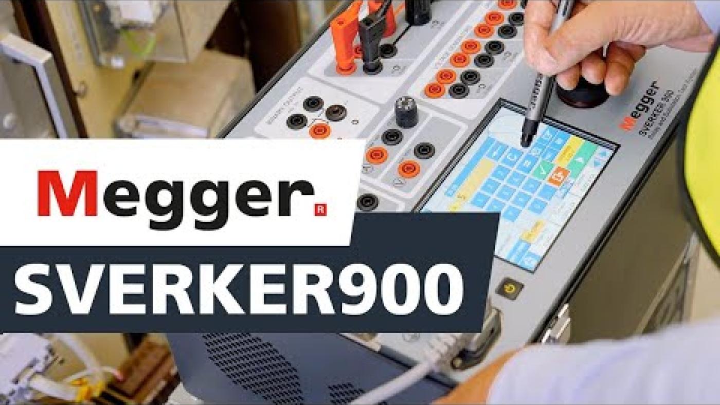
The instrument’s three current sources and four voltage sources can be individually adjusted with respect to amplitude, phase angle, and frequency. The fourth voltage source allows for testing of numerical relays that need a reference voltage simulating the busbar. Operating the relay tester is also incredibly easy thanks to its intuitive user interface presented on an LCD touch screen.

Zusätzliche Videos


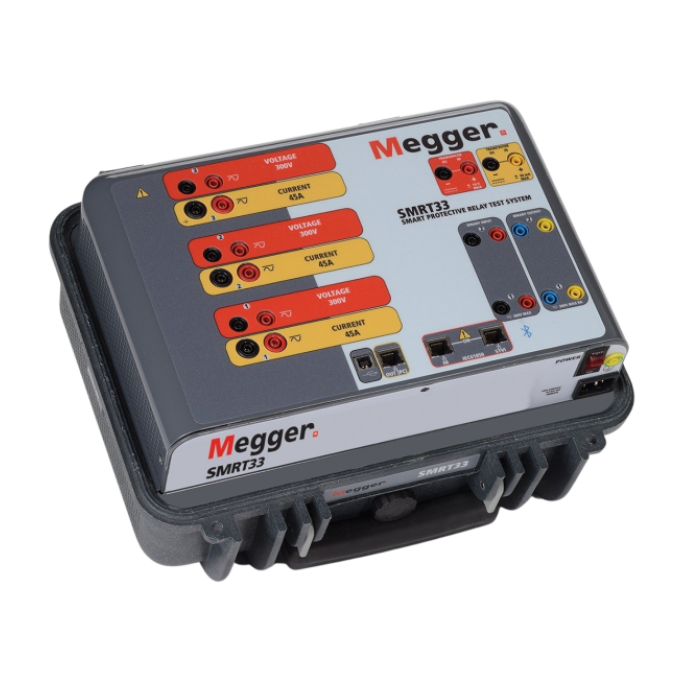
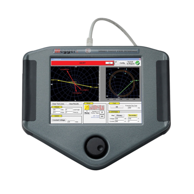
Verwandte Produkte

Verwendung Ihres Produkts


